ADLINK NuPRO-852 Full length PICMG1.0 Industrial Single Board Computer
Product Overview and Hardware Specifications
Core computing platform
CPU: LGA775 slot, Core 2 dual core, Pentium D/4, Celeron D, supports dual core, FSB 533/800/1066MHz (only Q965 supports 1066);
Chipset: North Bridge Q965/Q963, South Bridge ICH8; ITE IT8888G PCI to ISA bridge, fully compatible with old-fashioned ISA slots;
Memory: Dual 240pin DDR2 DIMM, 533/667/800MHz (Q965 exclusive 800), maximum total capacity 2GB, dual channel architecture.
Display, audio, network
Display: onboard Intel integrated graphics card, rear 15 pin VGA; BIOS adjustable shared video memory;
Audio: Optional, Realtek ALC888 HD audio, onboard JAUD1 front audio pin, requires external daughter card output 3.5mm interface;
Network: Marvel 88E8056 PCIe Gigabit Ethernet card, available in both single network and dual network hardware versions, with RJ45 Ethernet port and tri color LED to distinguish between 10/100/1000M speed and link activity, supporting PCIe and WOL remote wake-up.
Storage interface (mixed old and new storage)
2 x SATA II 3Gbps high-speed hard drive interface (ICH8 native, single drive per channel);
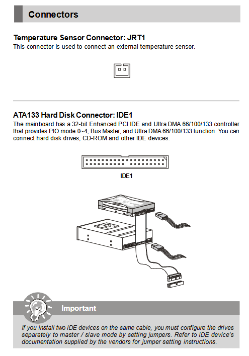
1 ATA13 IDE (JMicron bridge, compatible with old IDE hard drives/optical drives);
No floppy drive interface.
I/O peripheral resources
Serial port: COM2 fixed RS232; COM1 switches RS232/422/485 through JP1/JP2/JP3 jumpers, dedicated for industrial buses;
Parallel port: 26 pin J1 pin, supporting SPP/EPP/ECP modes;
USB: Two sets of F0USB1/F0USB2 onboard USB2.0 pins, totaling 4 channels;
Rear panel: composite PS/2 keyboard and mouse VGA、 1/2 gigabit network;
Expansion pins: JRT1 external temperature sensor, JFP1 front panel of the chassis.
Machinery and Environment
Size: 33.9cm × 12.3cm full length standard industrial control board;
Working temperature range of 0~50 ℃, suitable for enclosed industrial chassis with air duct environment;
The backplane gold finger simultaneously leads out PCI and ISA dual buses, compatible with traditional PICMG1.0 chassis backplane.
Hardware Installation, Connectors and Jumpers
2.1 Mandatory specifications for CPU and heatsink
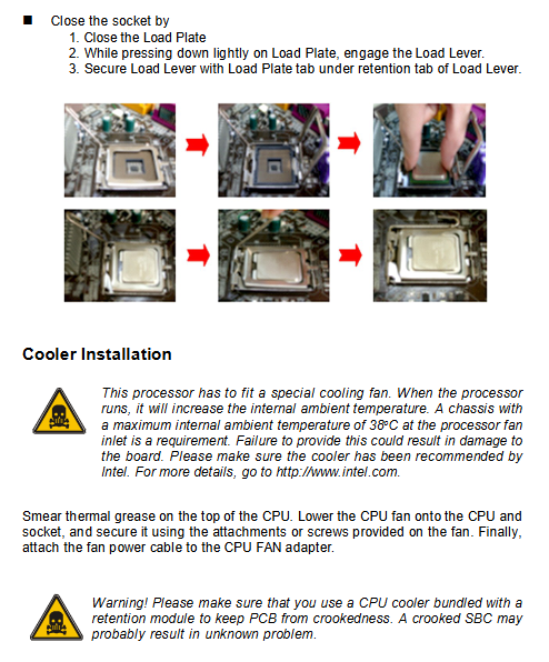
LGA775 standard ZIF installation process: lift the load rod, flip over the metal cover, remove the protective cover, align the CPU triangle logo with the slot, place it flat and then fasten the lock rod, and prohibit tilting and scratching the pins;
Mandatory requirement: It must be equipped with a dedicated heat sink with a back panel from the original factory. Ordinary downward pressure heat sinks can cause PCB bending and permanent damage; Apply thermal grease evenly to the CPU, and connect the fan to the CPU_SAN1 speed measurement power supply port.
2.2 DDR2 Memory Installation
240pin single notch foolproof slot, with automatic locking of the two end buckles when pressed vertically; Recommend opening dual channels for memory of the same specifications, dismantling and opening the plastic buckles on both sides, and storing them in an anti-static bag when idle.
2.3 Key power supply interfaces
JPW1 is a 4pin ATX 12V auxiliary power supply that must be plugged in to power on and provide stable power supply to the CPU core.
2.4 Complete definition of full board connectors
JFP1 20 pin front panel: power button, reset, power LED, hard drive LED, chassis speaker;
JAUD1 HD audio pin, paired with audio daughter card to achieve microphone/line input/output;
F_USB1/F_USB2: Two sets of dual USB2.0 pins with overcurrent protection pins;
IDE1 ATA133, SATA1/SATA2 dual serial hard drives;
CPU_SAN1 (4-pin variable speed fan);
COM1/COM2 serial port, J1 parallel port, JRT1 external temperature probe;
Rear I/O: PS/2, VGA, RJ45 Ethernet ports.
2.5 Three sets of core functional jumpers
JBAT1 (Clear CMOS): Short circuit 2-3 pins for 10 seconds after power failure, clear all BIOS parameters and passwords, restore to factory, and restore 1-2 after use;
JPWD1 (clear BIOS password): separate jumper, only clear boot/setup password, retain other hardware configurations;
JP1/JP2/JP3 (COM1 mode switching): Jumper combination switch RS232 (default)/RS422/RS485 bus, can enable terminal matching resistor.
2.6 Backboard Gold Fingers
The long gold finger on the right side of the board simultaneously outputs PCI and ISA buses, compatible with the backplane of old industrial control chassis compatible with ISA.
Phoenix Ward BIOS Complete Setup
Power on self-test prompt: Press F1 to enter BIOS, shortcut keys: F6 to load optimized default, F7 to load stable fault default, F10 to save and exit, ESC to abandon modifications; There are 7 main menus in total.
Main (Basic Information)
System time and date, automatic detection of four-way storage devices (IDE/SATA), read-only display of total memory, and manual configuration of hard disk LBA/CHS parameters.
Advanced (core advanced settings, divided into multiple sub items)
CPU Features: TM2 temperature control, C1E energy-saving frequency reduction, XD anti overflow virus protection, maximum CPUID limit;
Basic BIOS: boot NumLock, A20 address, boot sector virus alarm, OS adaptation with memory greater than 64MB;
Chipset settings: 15M-16M ISA memory hole switch, onboard video memory size, DVMT dynamic video memory, priority graphics card (onboard/PCIe);
Integrated Peripherals:
Onboard dual gigabit network card switch, PXE boot ROM switch;
USB 2.0 global, DOS keyboard and mouse support;
Super IO: Two serial port addresses, parallel port mode, power-off recovery strategy (shutdown/power on/last state);
Power management ACPI: S1/S3 sleep mode, hard disk timed sleep mode, CPU temperature control and speed regulation, PCI device remote wake-up, RTC timed power on;
PnP/PCI: Manually allocate IRQ/DMA to ISA card, reset ESCD resources, PCIe load size settings.
Boot (Start menu)
Customize the first/second/third boot device (LAN/CD-ROM/hard drive/USB), adjust the priority of hard drive boot, and enable/disable other device boot.
Security (security menu)
Administrator password (all parameters can be modified), user password (view only), BIOS firmware write protection (antivirus tampering firmware, needs to be temporarily turned off when refreshing BIOS).
System (System Summary)
Read only the hardware list of the entire machine, and follow the startup and shutdown rules (all errors reported/ignore keyboard/no errors reported).
PC Health (Hardware Monitoring Panel)
Real time reading of CPU/motherboard temperature, CPU fan speed, Vcore/memory/3.3V/5V/12V voltage channels; Intelligent temperature control fan threshold customization, automatically increasing speed at high temperatures.
Exit (Exit option)
Save exit, do not save exit, load failure conservative default, load performance optimal factory default.
Horizontal comparison of NuPRO-852 in the same series
Compare NuPRO-841 (845GV platform)
Upgrade LGA775 Core platform, DDR2 memory, PCIe Gigabit dual network, native SATA II;
Retain ISA bridge and 485 serial port to maintain compatibility with older devices;
841 has a single 100MB, no SATA, and DDR1 memory limit of 2GB.
Compare NuPRO-935 (Q35 PICMG1.0)
The Q965 chip has stronger performance and supports 1066MHz FSB;
935 comes standard with TPM security chip, NuPRO-852 has no security encryption module;
product positioning
Mid end compatible full-length industrial control board, suitable for the transformation of existing ISA acquisition card equipment and automation production lines that require SATA solid-state+dual gigabit network, balancing old and new storage/bus.