ADLINK NuPRO-775 Half length Socket370 Industrial Single Board Computer
Chapter 1 Product Introduction
1.1 Packing List
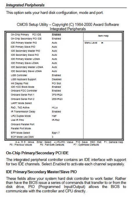
Motherboard body, this manual, IDE ribbon cable, floppy drive ribbon cable, 2 serial port blocking cables+1 parallel port cable, optional dual USB ribbon cable, matching driver CD (chipset/VGA/network card driver+monitoring tool).
1.2 Product positioning and architecture
Industrial motherboard based on Intel i82810 GMCH chipset, suitable for harsh industrial environments, with Socket370 slot supporting Celeron/Pentium III processors; Equipped with Winbond W83627HF super I/O chip, it comes with hardware monitoring, chassis opening detection and safety functions, and uses ATX power supply.
1.3 Core functional characteristics
CPU: Celeron 300~533MHz, Pentium III 500E/550E and higher, front-end bus 66/100MHz; Second level cache integrated into CPU
Memory: Single 168 pin DIMM slot, maximum 256MB PC100 non buffered SDRAM
Display: The onboard i810 integrates VGA, built-in AGP2X, 24 bit 230MHz RAMDAC, with a maximum output of 1600 x 1200@85Hz , DDC2B compatible
Peripheral interface: 2 channels of 16550 RS232 serial port, 1 channel of SPP/ECP/EPP high-speed parallel port; 2-channel USB 1.1 (overcurrent protection)
Network: Intel 82559 PCI 10/100M adaptive network card, supporting Wake On LAN, Alert on LAN II, IEEE802.3X traffic control
Industrial specific functions: programmable watchdog timer, overall hardware health monitoring, modem ringing startup, Y2K millennium compatible BIOS, DMI hardware information reading
1.4 Complete electrical specifications
BIOS: Award Plug and Play BIOS, 512KB Intel 82802AB firmware hub, supports power management
Storage: Dual EIDE channels (up to 4 IDE devices, supporting Ultra DMA/66), floppy drive interface compatible with full specification floppy disks
Electrical protection: serial ESD 2KV, parallel ESD 4KV; Power specifications+ 5V@10A The+ 3.3V@10A The+ 12V@0.6A The -12V@130mA The+ 5VSB@0.6A
Environmental parameters: working temperature 0~70 ℃, humidity 5%~95%, no condensation; Physical dimensions 185mm × 122mm half length PCI board
Bus: Fully compliant with PCI 2.1 specifications
1.5 Intelligent monitoring function (Intelligence)
Hardware monitoring: CPU temperature, external system temperature, chassis cover opening detection, CPU/chassis fan speed, real-time collection of various voltages
Wake up/shutdown mechanism: Win98 ATX soft shutdown, modem incoming call power on, network card remote power on (WOL), timed alarm clock power on
Management functions: Alert on LAN II pushes hardware failure alerts through Ethernet, APM advanced power management, Millennium Bug compatible BIOS
Attached are the layout diagram of motherboard components and mechanical dimension engineering drawings, indicating all interfaces, chips, and jumper positions.
Chapter 2 Hardware Installation
This chapter explains the practical steps for configuring CPU, memory, jumpers, connectors, and watchdog.
2.1 CPU installation
Install Celeron/Pentium III into Socket 370 slot and align it with the CPU notch; The radiator must be installed to ensure complete fit, otherwise it will overheat and crash; After installation, match the CPU external frequency through JP1/JP2 jumper.
2.2 Memory installation
Single 168 pin DIMM slot, supporting 16/32/64/128/256MB SDRAM, with a maximum total capacity of 256MB.
2.3 Jumper Definition (JP1/JP2/JP3/JP4)
JP1/JP2: Set CPU and SDRAM clock (66MHz/100MHz/automatic recognition three levels)
JP3: Power button jumper
JP4: Standby power jumper
2.4 Definition of pins for all onboard connectors
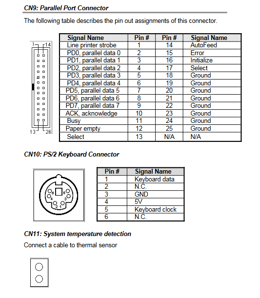
Please provide a general diagram of the connector locations, explaining the functions and pins of the CN series interfaces one by one
Storage: CN1 floppy drive, CN3 main IDE, CN2 secondary IDE
Communication: CN5 COM1, CN4 COM2 serial ports; CN6 modem ringing trigger; CN8 dual USB
Human computer interface: CN9 parallel port, CN10 PS/2 keyboard, CN13 PS/2 mouse, CN14 VGA display
Network: CN15 RJ45 Ethernet port, dual LED indicating link status/data flashing respectively
Monitoring/power supply: CN11 system temperature sensor; FN1 3-pin CPU fan power supply (with speed detection)
2.5 Watchdog Timer
Function: Automatic reset in case of system crash, timing unit can be selected from 0 to 255 seconds/minute
Bottom level operation: Operate W83627HF logic device 8 registers through I/O addresses 2Eh/2Fh, provide 8086 assembly complete example code (15 second timeout reset)
Supporting tools: The CD provides watchdog subroutines for DOS, Win95/98/2000/NT, which can be directly called.
Chapter 3 BIOS Configuration (Award BIOS Setup)
Press Del to enter the settings interface when starting up, which includes 10 complete configuration menus covering all hardware, performance, power, and safety parameters:
3.1 Standard CMOS Features
System time and date, IDE hard disk automatic detection/manual parameters, floppy drive specifications, display type, startup error shutdown strategy.
3.2 Advanced BIOS Features
Virus boot sector protection, CPU level 1/2 cache switch, boot self-test acceleration, boot device priority, default state of numeric keypad, boot password security option, S.M.A.R.T hard disk health check, etc.
3.3 Advanced Chipset Features
I810 memory timing (CAS latency, RAS pre charging), BIOS/VRAM cache, 15M-16M memory reserved for ISA card, onboard VRAM window size, PCI latency transactions.
3.4 Integrated Peripherals
IDE channel switch, PIO/UDMA hard disk mode, USB controller/USB keyboard support, serial port parallel address and working mode (SPP/ECP/EPP), infrared UART configuration.
3.5 Power Management Setup
ACPI global switch, graded energy-saving strategy, display shutdown mode, CPU overheating and frequency reduction, modem/network card remote wake-up, chassis intrusion detection, timed alarm startup, hard disk idle power-off.
3.6 PNP/PCI Resource Configuration
ESCD resource reset, IRQ/memory resource automatic/manual allocation, PCI/VGA color palette correction.
3.7 PC Hardware Health Status
Real time reading of CPU/system temperature, fan speed, core voltage, and various ± 3.3/± 5/± 12V voltages; Set CPU high temperature alarm threshold and automatic shutdown temperature.
3.8 Frequency and Voltage Control
DIMM/PCI clock automatic detection, CPU doubling/external frequency adjustment, and spread frequency setting.
3.9 Auxiliary functions
Load Fail Safe Defaults: Load stable and conservative default parameters for faults
Load Optimized Defaults: Load original high-performance optimization parameters
Administrator/User Level Startup Password Settings
Two sets of operation logic for saving and exiting/not saving and exiting
Chapter 4: Intel 810 Chipset and VGA Driver Installation
4.1 Chipset driver (INF configuration file)
Supported systems: Win95 full version, Win98 original/second version
Installation process: Close the background program, run the CD Setup. exe, agree to the license, restart the automatic hardware recognition, manually specify the driver path to complete the installation.
4.2 Onboard VGA graphics card driver
Win95/98: Extract graphics driver package, run Setup, restart to take effect
Windows NT4.0: SP4 service pack must be installed first, and then graphics card driver installation must be performed to adapt to i810 integrated display output.
Chapter 5: Installation of Intel 82559 Network Card Driver
5.1 Introduction to Network Card Hardware
PCI bus 10/100M adaptive, bus master control, supports full/half duplex, remote wake-up Magic Packet, compatible with IEEE802.3u standard.
5.2 Cross system driver support list
Covering multiple operating systems such as Novell NetWare, Windows full range, SCO Unix, Linux, OS/2, DOS group driver, etc.
5.3 Onboard diagnostic tools
The CD comes with an 8255x configuration diagnostic program, which can be executed under DOS and provides 5 core functions:
Automatic setup: Automatically identify hardware and install drivers
View adapter configuration: View MAC address IRQ、 Bus speed, duplex mode
Test adapter: Hardware Loop/Network Connectivity Self Test
Install network drivers: Install corresponding drivers for Microsoft/Novell/other operating systems
View Help files: View driver documentation
Chapter 6 Hardware Doctor Hardware Monitoring Tool
Windows platform monitoring software with W83627HF super I/O chip (bilingual in Chinese and English, supporting Win95/98/NT):
Core monitoring items
Voltage monitoring: Vcore,+3.3V,+5V, ± 12V, standby voltage, custom high and low thresholds, red highlighted pop-up alarm and buzzer alarm for exceeding the standard
Fan speed: up to 3 fan acquisition channels, only supports 3-pin fan speed detection, triggering warning below threshold
Temperature monitoring: CPU temperature, external system temperature sensor, high temperature automatic warning
Chassis lid opening detection: When the chassis is opened and a continuous pop-up window appears, entering the password is required to clear the alarm
Software operation function
File menu: Restore default threshold, save custom parameters, exit program
Tools configuration: Select monitoring items, fault alarm triggering conditions, buzzer switch
Backend residency: Minimize to the taskbar, continuously collect real-time hardware data, and protect the CPU and power from damage caused by overheating/undervoltage.