ETEL DSB2-P Digital Servo Amplifier
Product core positioning
DSB2-P is a high-performance direct drive dedicated single axis digital servo power amplifier, integrated with dual 16 bit DSP, supporting position/pseudo speed/force three loop control, suitable for single-phase, two-phase, three-phase linear/torque ironless direct drive motors, compatible with brushed DC and closed-loop stepper motors; It can be used independently or cascaded up to 31 axes through ETEL-BUS daisy chain, with ETEL Tools upper software debugging, for high-precision semiconductors, optical platforms, and precision automation equipment.
Complete differentiation of the four major hardware models
DSB2-P is divided into four series: rack without power supply, rack with heat dissipation, shell without built-in power supply, and shell integrated power supply, suitable for different cabinet scenarios:
1. Rack module (DSB2Pxx1, 6U 10F, no built-in power supply)
Size: 261.8 × 50.6mm, weight 1.1kg; single servo board integrated design, power and control circuit electrical isolation;
Power supply: External 24-340VDC DC power supply (recommended ETEL DSO-PWR rack power supply);
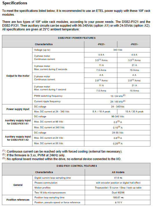
Current specification: Continuous 4.9A, peak value of 11A for 2 seconds; suitable for small and medium power direct drive multi axis rack systems.
2. Rack with heat sink (DSB2Pxx2, 6U 14F, no built-in power supply)
Equipped with integrated high-power heat dissipation fins, peak current is increased;
Divided into three levels: PX32/PX42/PX52: maximum 2-second peak value of 42 A, 1-second peak value of 56 A;
Compatible with multi axis control cabinets for high thrust linear motors and high torque rotary torque motors.
3. Independent shell without power supply (DSB2Pxx3, single box)
Integrated metal casing, external DC 24-340V power supply;
Size 318 × 168.7 × 65.2mm, weight 2.8kg;
Suitable for single axis independent equipment and small workbenches, without the need for standard 19 inch cabinets.
4. Independent shell with built-in power supply (DSB2Pxx4, integrated with the whole machine, most commonly used)
Internal double-layer board: servo control board+AC input power board, directly connected to 84~240V single-phase/three-phase mains power;
Optional motor short-circuit relay (model suffix -2xx), stop and short-circuit the motor winding to achieve passive braking;
Support external regenerative braking resistor interface, suitable for high-frequency reciprocating motion;
Weighing 5.3kg, it can be quickly deployed on site with a single axis without the need for an additional DC power supply.
Universal hardware architecture across the entire system
The whole machine is divided into two isolation sections: control isolation area and IGBT power main circuit
Control side: dual DSP, encoder acquisition, optocoupler IO, EBL/ETEL-BUS communication, DC-DC auxiliary power supply;
Power side: Bus overvoltage/overcurrent detection, di/dt current limitation, three-phase IGBT bridge, current AD sampling;
Isolation design: High voltage isolation layer between strong and weak electricity, auxiliary GND connected to the chassis through a 22nF capacitor to suppress common mode interference.
Full classification description of electrical interfaces
All connectors of the whole machine are divided into 6 categories, all of which are marked with high voltage/ESD warnings. The manual provides complete pin definitions and wiring schematics:
3.1 Encoder interface (J1/J9/J10)
J10 (TTL differential encoder, DB15)
Compatible with RS422 A/B/Z three-phase differential, with a maximum input of 10MHz; Support pulse/direction upper command input; Non differential encoders require an external 1k pull-up resistor; +The 5V encoder is powered by F7 500mA fuse protection.
TTL encoder waveform
Pulse direction mode timing
J1 (analog sine cosine encoder, DB9)
There are two hardware versions: 1Vpp and 11 μ A current type, which are not interchangeable; Sine/cosine 90 ° phase signal, built-in up to 2048 times subdivision, compatible with grating ruler and high-precision magnetic encoder.
Simulate encoder waveform
J9 (Digital Hall+Motor Temperature PTC)
Three way Hall sensor input recognition of motor magnetic poles; External PTC thermistor detects winding overheating, and over threshold driver locks for protection; Input optocoupler isolation, supporting external power supply of 5-15V.
3.2 User IO Interface J2 (DB15 Optocoupler Isolation)
Analog input AIN1: ± 10V, 14 bit AD sampling, used for force control and external simulation settings;
6-way isolated digital input DIN: universal for limit, origin, and emergency stop, triggered by external 15-28V;
3-channel isolated digital output DO: servo ready, fault, motion completed, external 24V drive relay;
Onboard+15V auxiliary power supply (F3 250mA fuse), capable of supplying power to sensors.
3.3 Communication interface (J3/J4/J5/J6 RJ45 network port)
Two bus systems, supporting single PC and multi axis daisy chain networking:
EBL (ETEL Bus Lite, J5): PC standalone communication, RS232/RS422 optional, baud rate 9600~115200, used for ETEL Tools debugging and single axis upper control;
ETEL-BUS (EB, J3 output/J4 input): Multi axis daisy chain dedicated RS422460k high-speed, up to 31 DSB2-P cascaded;
J6 download port: Insert a dedicated download key to force firmware refresh mode, supporting RS232 backup EB bus.
3.4 Motor power interface J7/J7B
J7 standard 5-pin power seat: compatible with single-phase/two-phase/three-phase motors, PH1~PH4 output three-phase power, PE forced protection ground;
J7B model with short-circuit relay: Built in winding short-circuit circuit, stopping the short-circuit motor to achieve energy consumption braking; Equipped with J16 relay control terminal and external 24V control signal.
3.5 Power input interface (by model)
Rack model J11: DC 24-340V bus+96/24V auxiliary dual input; INR power on slow start signal, combined with ETEL power supply to complete capacitor pre charging;
J15 shell without power supply: external DC power+auxiliary two Phoenix terminals;
Built in power supply models J14/J13: three-phase/single-phase 84~240V mains input, independent auxiliary power supply circuit;
J12 External Regenerative Resistance Terminal: High frequency reciprocating equipment is equipped with an external discharge resistor with a minimum resistance of 39 Ω/3.8kW.
3.6 Expansion Board Interface J8
Reserve DSO-CAN, DSO-PROFIBUS, DSO-SIO option board slots, expand fieldbus, and add 8 additional DI/DO channels.
Power and Control Core Specifications
1. Current loop performance (full system one)
CTI current interruption period of 41.6 μ s, dual loop PI regulation;
PWM carrier 12kHz/24kHz (firmware 3.xx only 24kHz), current ripple 24/48kHz;
Built in di/dt slope limit to suppress power on surge current; There are three current limits: continuous, 2-second peak, and 1-second peak, to prevent the motor from overheating and burning out.
2. Motor control ability
The STI cycle of the position ring is 166.67 μ s, supporting trapezoidal, S-curve, and table lookup custom cam trajectories;
Built in 5420 line local motion sequence storage, no need for continuous PC control;
Pulse direction command up to 3MHz, ± 10V simulated force/velocity given;
Supports open-loop stepper, closed-loop direct drive, and DC brushed full motor types.
3. Supporting software ETEL Tools
Support Windows 9x/2000/XP, five major tools: driver parameter configuration, digital oscilloscope, command terminal, sequence editor, unit conversion; It can automatically adjust the current/position loop PI for AUT and collect motion waveform tuning.
Installation, heat dissipation, and EMC wiring specifications
1. Requirements for cabinet installation
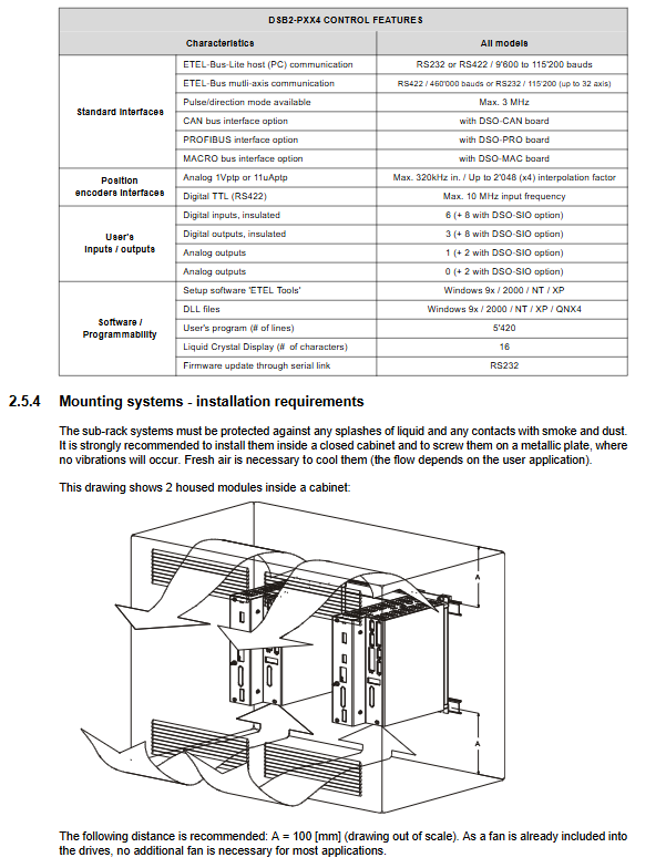
Rack model: Standard 19 inch 6U subrack vertically installed, with 100mm ventilation space reserved above and below, bottom air inlet and top air outlet;
Shell model: fixed with metal backplate screws, with a ventilation gap of ≥ 100mm for the entire machine;
Forced cooling: High peak current models must have cabinet axial fans for forced air cooling, and natural cooling is only suitable for light load conditions.
Cabinet ventilation layout
2. Mandatory EMC Cable Standard (Core Installation Chapter)
Motors and encoders must have double-layer shielded cables, and aluminum foil simple shielding is prohibited;
The cable shielding layer covers the entire metal connector shell 360 °, and it is prohibited to ground a single tail wire;
Separate the power cable and signal cable distribution trough to avoid parallel long-distance wiring;
360 ° crimping and shielding of metal wire clamps for regenerated resistors and relay cables, with standard examples taken in practice;
Real shot of shielding of regenerated resistor cable
The whole machine protection ground PE is connected first, and all grounding points are collected to eliminate ground loop interference.
Supporting documents and application scenarios
1. Complete set of technical documentation
DSB2-P hardware manual (this document, hardware interface/power);
DSB2-P operating software manual (motion, command, parameter tuning, which is the same system as the previous DSC2P manual);
EBL Bus Communication Manual (Upper Communication Protocol);
DSO-PWR Power Supply Manual (Supporting Rack DC Power Supply).
2. Target application
Suitable for ETEL’s full range of ironless linear and torque direct drive motors, used for:
Semiconductor wafer precision positioning platform;
Optical detection and laser microfabrication equipment;
High precision three coordinate and vacuum displacement table;
Multi axis synchronous automated testing equipment;
Combined with the cPCI industrial control and DSC2P motion controller mentioned earlier, it forms a complete high-end direct drive motion control system.