ETEL DSC Series (DSC2P/DSC2V/DSCDP/DSCDL/DSCDM) Operation and Software Manual
Applicable products and firmware versions
Covering 4 types of hardware: single axis DSC2P/DSC2V, dual axis DSCDP/DSCDL/DSCDM; Clearly define the minimum firmware for each model, the supporting versions of DSMAX/DSTEB and ETEL Tools (ETT 4.11), and refer to the corresponding hardware manual (such as DSCDL hardware manual) for hardware interfaces and electrical specifications. This article only explains the internal principles, wiring debugging, upper software, and motion programming.
Chapter A: Controller Bottom Hardware Architecture and Operating Principles
1. Dual DSP layered closed-loop control architecture
Adopting dual ADI SHARC floating-point DSP division of labor operation, dual layer PI closed-loop:
Trajectory DSP: interpolation calculation, local sequence, slow STI interrupt
Adjusting DSP: Position loop, current loop, high-speed closed-loop (CTI/FTI interrupt)
Complete link: Upper target point → Trajectory generator → Position loop outputs target force Fc → Three phase sine current generator → Current PI loop outputs driving motor; The encoder provides real-time feedback to correct position errors.
2. Three phase sine current generation logic
Built in 2048 point sine lookup table, three-phase phase difference of 120 °, matching current output based on motor electrical angle, eliminating direct drive torque fluctuations; Phasing identifies magnetic poles during power on phase initialization, with three modes: constant current, short pulse, and Hall effect.
3. Eight types of motion trajectory algorithms
The controller supports two types of trajectories: linear and rotational. Mass production equipment defaults to using S-curve (3-step acceleration, no mechanical impact), and Step step is only used for debugging:
Fundamentals: step, trapezoid, rectangle, S-shaped curve
Advanced: Custom lookup table LKT, infinite rotation, precomputed contour, electronic cam CAM
LKT table lookup can store up to 2000 points and supports custom shaped cam trajectories. It has a dual layer smooth output of STI coarse interpolation and FTI fine interpolation.
4. Three layer hardware timed interrupt (core real-time timing)
All movements, communications, and closed-loop rely on fixed hardware interrupts, with different cycles for different models:
Interrupt function DSC2P cycle DSCDL cycle
STI slow interrupt trajectory, local program, RTI real-time interrupt 166.67 μ s (6kHz) 500 μ s (2kHz)
FT fast interrupt position loop, trajectory interpolation, EBL communication 41.67 μ s (24kHz) 55.56 μ s (18kHz)
CTI current interruption three-phase current PI closed-loop 41.67 μ s (24kHz) 13.89 μ s (72kHz)
The timing values can be read and converted through the M-series monitoring register.
5. Three types of complete machine communication topologies
Single machine EBL2 mode: PC serial port directly connected to single axis, baud rate 9600~115200 can be modified through K195 parameter.
DSMAX/DSTEB main station TEB multi axis: PCI card as the upper level, TEB bus daisy chain, up to 31 axis global synchronization, supports multi axis interpolation.
Micro host μ – Master: A DSC2P serves as the 0 host, with EBL connected to PC and TEB cascaded slave axes, without the need for a PCI master card, but without multi axis interpolation capability.
6. Complete syntax system for instructions and registers
(1) Three letter instruction system
Standard format: Instructions <Axis>[=Parameter 1, Parameter 2], supports batch execution of single axis, all axes (!), and axis mask (%), with built-in XAC accumulator for four-way/logical operations; Supports hundreds of commands such as jump, wait, move, and fault clearing.
(2) Register 6 major categories
K parameter register: motor, encoder PID、 Limit configuration (4 layers of storage depth 0~3)
M monitoring register: read-only, real-time position/current/temperature/fault status
X User Variables: Program Custom Storage
R (RTI real-time interrupt), E (position trigger), L (lookup trajectory LKT), F floating-point register, S local sequence register
(3) Register operation rules
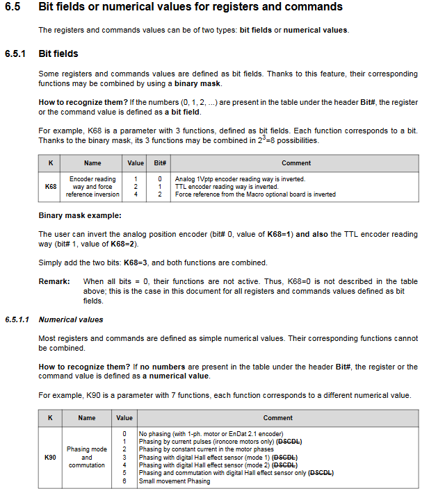
Supports read-write, arithmetic operations, and bit mask combination configuration, distinguishing between pure numeric/bit field registers.
Chapter B: Hardware Wiring and ETEL Tools (ETT) Upper Level Debugging Software
1. Standard hardware installation process
Mandatory wiring sequence: PE protection ground → power supply → motor power line → encoder, IO; it is strictly prohibited to plug or unplug the encoder when it is live.
Two hardware wiring schemes: standalone EBL and DSMAX multi axis TEB daisy chain.
Power on self-test: The LCD displays the model, firmware, and shaft number. Only when there are no errors can the parameters be loaded.
2. ETEL Tools software (ETT V4.11)
Operating environment: Windows 9X/2000/XP, minimum 166MHz CPU, 64MB memory
The five core tools of the software main interface, accompanied by advanced tools:
Drive Setting Drive Wizard (Beginner’s Choice)
One click completion of the entire system configuration process: backup old parameters → identify controller → select motor → encoder → initialization mode → zero return mode → inertia input → AUT automatic tuning, generating all K parameters automatically.
Supports ETEL’s own linear/torque motors and third-party BLDC and stepper motors, compatible with analog sine, TTL, and EnDat2.1 encoders.
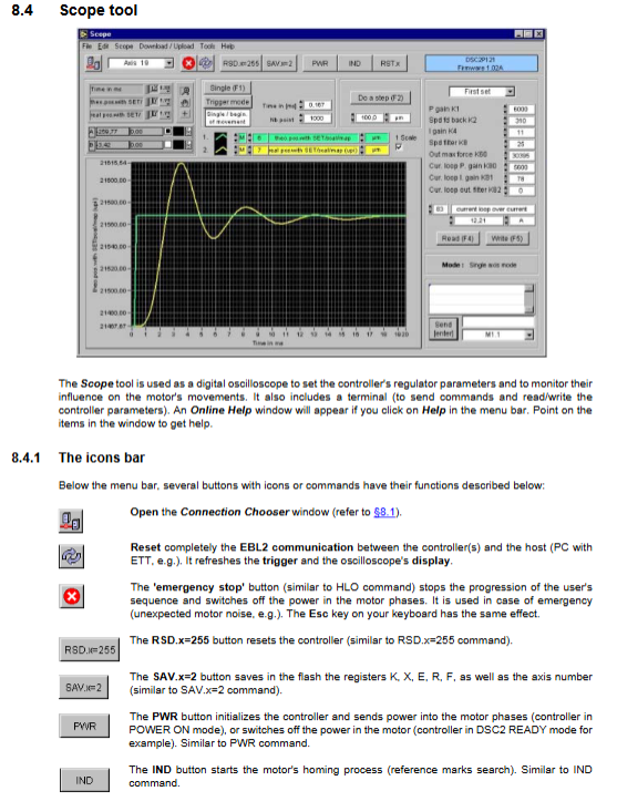
2. Scope Dual channel Digital Oscilloscope
Collect position, velocity, and three-phase current waveforms for step response identification and PID fine tuning, with built-in trigger sampling function.
3. Terminal Command Terminal
Directly issue three letter instructions, read and write registers, dedicated for manual debugging and troubleshooting.
4. Editor Sequence Editor
Grammar highlighting for writing local offline motion programs, supporting downloading to controller Flash for offline operation.
5. Unit Converter Unit Conversion Tool
Mechanical mm/° and bidirectional conversion of pulse counting, suitable for screw and linear platforms.
6. Advanced tools: Multiscope multi axis synchronous sampling, register batch editor, firmware downloader, parameter backup tool.
3. Steps for establishing software communication
Open Connection Chooser, select EBL serial port/DSMAX/DSTEB bus, distinguish between reset/non reset connection modes, and support simulation debugging.
Chapter C: Basic and Advanced System Functions
1. Basic essential functions (essential for device operation)
Axis address configuration: Hardware DIP dialing or AX software instructions, axis numbers 0-30 cannot be repeated; Read the controller serial number and firmware version.
Encoder fully compatible: analog 1Vpp sine, EnDat2.1 absolute value, TTL increment, open-loop step four modes, software settings for frequency doubling and disconnection monitoring.
Multi layer security protection
Travel: Soft and hard limit, travel error limit
Electrical: Peak/continuous current limit, bus overvoltage and undervoltage, fuse detection
Thermal protection: Motor PTC overtemperature shutdown
Fault handling: RST machine reset, CPE clearing alarm, dynamic braking shutdown
Motor initialization&zeroing Homing
Phasing phase recognition: solves the problem of unknown upper electromagnetic pole, supports three modes: constant current, short pulse, and Hall (K90 parameter configuration);
Multiple zeroing schemes: origin switch, mechanical stopper, encoder Z-phase index, configurable zeroing speed and offset.
AUT automatic tuning: One click recognition of motor resistance, inductance, and back electromotive force, automatically generating current/position loop PID gain.
Basic motion instructions: SET coordinate reset, linear/rotational S-curve positioning, continuous jog, real-time monitoring of position, velocity, and current.
2. Advanced customization function (specialized for high-precision equipment)
Complex motion mode
LKT electronic cam lookup, infinite reciprocating rotation, MMC non-stop continuous interpolation, CAM master-slave electronic gear, segmented start stop STA/STI, deceleration stop BRK.
Digital/Analog IO System
Each axis is independently isolated DI/DO; DI hardware locks real-time position; ± 10V analog input/output, used for external force control settings.
RTI hardware real-time interrupt
Position IO、 Fault conditions trigger in microseconds, immediately jump to local subroutines, adapt to laser synchronization and visual positioning.
Multi channel position trigger
Custom point automatic output DO, trigger interrupt, switch motion, support batch point FIFO caching.
External given mode: pulse direction, analog voltage speed/force control external command.
Chapter D: Offline Programming of Controller Local Sequence
The controller is equipped with built-in program storage, eliminating the need for a PC to continuously issue instructions. The complete programming syntax is as follows:
Waiting for instructions: waiting for axis idle WTB, waiting for IO level WBS, waiting for position threshold WPL.
Determine jump
Unconditional JMP; Condition TST/JEQ/JNE/JLT/JGT; Subroutine CAL/RET/POP; Program stop HLT/HLB/END ends; Tags 0~511 (79/80 are system specific).
Computing system
XAC accumulator completes addition, subtraction, multiplication, division, bit and/or shift; Floating point registers support high-precision decimal operations; CLX clears user variables.
Batch examples
The appendix provides dozens of complete replicable program examples including AXI, AUT, CAM, RTI, trigger, loop, motion, etc.
Chapter E: Appendix Reference List
All three letter instruction index: each instruction function, parameter, and compatible controller model;
K parameter complete table: divided into four sets: DSC2P/DSCDP/DSCDL/DSCDM, covering gain, communication, limit, and return to zero;
M Read only monitoring register list: definitions of current, timing, temperature, and fault bits;
Alarm fault code+troubleshooting plan;
Unit conversion formula: Force, velocity, time, angle/length unit conversion standard.
Overall application scenarios of the product
The ETEL DSC series is a high-end direct drive dedicated servo controller, paired with its own linear/torque ironless motor, used for ultra high precision automation equipment:
Semiconductor wafer vacuum translation stage, precision optical alignment equipment;
Laser microfabrication, electronic cam printing, high-speed cutting equipment;
Multi axis gantry synchronous, high-precision three coordinate detection platform;
Laboratory precision displacement table and automated ATE testing equipment;
Can be paired with cPCI industrial control host and DAQ acquisition card to build a complete high-end measurement and control system.