ADLINK PCI/cPCI -/LPCI -/LPCIe-723X series 32 channel isolated digital I/O board
Full range product models and core positioning
The 723X series is equipped with optoelectronic isolation, eliminating ground loops and protecting industrial control hosts. It is divided into four categories of functional boards and covers four bus specifications: standard PCI, 3U CompactPCI, low version LPCI, and low version PCIe
1. PCI/cPCI/LPCIe-7230 (16DI+16DO mixed isolated digital IO)
Channel: 16 isolated digital inputs+16 isolated digital outputs
Isolation withstand voltage: PCI/cPCI-7230 is 5000Vrms; LPCI/LPCIe-7230 is 2500Vrms (excluding cables)
Bus specifications: Standard 32-bit 5V PCI/3U CompactPCI/3.3V/5V low version PCI/x1 channel low version PCIe
Interface: PCI version 37 pin D-Sub; CPCI/LPCI/LPCIe version 50 pin SCSI-II
Input characteristics: Maximum 24V DC input protection; Logic low 0~1.5V, logic high 5~24V, input impedance 1.2k Ω; supports 2 external interrupt sources
Output characteristics: Darlington transistor current output; Single route full load 500mA@100 %Duty cycle, current derating occurs when all channels output simultaneously; External power supply VDD range 5~35VDC
Transmission rate: IO throughput of 10kHz
2. PCI-7233 (pure 32 channel isolated digital input, with COS state change detection)
Channel: 32 isolated DI channels, no output channel
Core features: COS (Change of State) level jump detection, dual interrupt architecture
INT1: Interrupt triggered by any level change in channels 0-15; INT2: Interrupt triggered by any level change in channels 16~31
Isolation withstand voltage: 5000Vrms; Input electrical parameters consistent with 7230; 37 pin D-Sub interface
Applicable scenarios: scenes that require real-time capture of switch changes and event triggered data collection
3. PCI-7234 (32 isolated digital outputs, sink current type)
Channel: 32 Darlington isolated outputs, only DO without DI
Drive: Inject current output, load current flows into the board; single channel 500mA@100 %Duty cycle, all channels output derating simultaneously
Voltage resistance 5000Vrms, external power supply 5-35VDC, 37 pin D-Sub interface
4. PCI-7234P (32 isolated digital outputs, pull current Source type)
Channel: 32 isolated DO channels, output current flows from the board to the load
Current derating is different from 34: all channels output simultaneously only 260mA@10 %Duty cycle; Other electrical, isolation, and interface parameters are the same as PCI-7234
Universal hardware specifications (full range)
Temperature and humidity: working at 0-60 ℃; Storage -20~80 ℃; Humidity 5~95%, no condensation
Power supply: The power consumption of PCI slots on each board is different, and the DO channel must be connected to an external power supply of 5-35V (VDD pin)
Size: Different bus board sizes are distinguished, CompactPCI、 Standard PCI and low version PCIe have gradually reduced in size
Connector matching terminal board: ACLD-9137-01 (37 pin universal), DIN-37D-01 (rail mounted 37 pin), DIN-50S-01 (rail mounted 50 pin SCSI), matched with dedicated cables.
Hardware Installation Process
1. Open box inspection checklist
Standard configuration: User manual, 723X board, Linghua software CD, software installation guide; Contact the dealer for missing/damaged items and keep the packaging.
2. Anti static standards
The board contains sensitive chips, and grounding anti-static pads and anti-static wristbands must be used for operation; Do not plug or unplug with power on, and do not power on after damage.
3. PCI Plug and Play Hardware Installation Steps
Turn off the main power of the computer and peripherals, and open the chassis;
Choose any available PCI slot (white short slot, distinguish ISA/EISA);
Touching the metal of the chassis releases static electricity, while holding the edge of the board without touching the components;
Insert smoothly into the slot and secure the baffle screw;
Cover the computer case and complete the hardware installation.
4. Windows system device recognition
After the system is started, PnP automatically recognizes the NuDAQ acquisition card. The first installation requires specifying the driver path, refer to the accompanying “Software Installation Guide”.
5. Definition of connector pins (by model)
Unified identification standard:
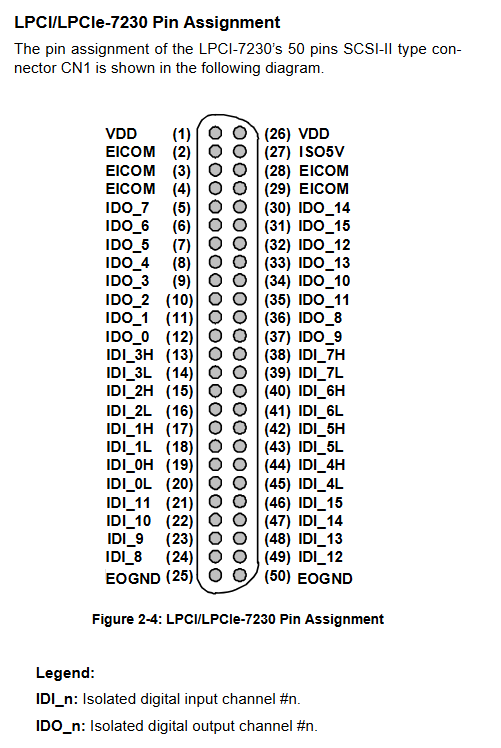
IDI-n: nth isolated digital input; IDO-n: nth isolated digital output
EICOM/IGND: isolated input common ground; EOGND: Isolated output return ground
VDD: Output drives external power input (5~35VDC, drives freewheeling diode protection relays/solenoid valves and other inductive loads)
DI_nH/DI_nL: cPCI/LPCI/LPCIe-7230 differential input high and low ends
Differentiation of interfaces for each model:
PCI-7230:37 pin D-Sub, 16DI+16DO, including VDD, EOGND, EICOM common terminal
CPCI/LPCI/LPCIe-7230:50 pin SCSI-II, supports differential DI, and adds ISO5V isolated 5V output
PCI-7233: 37 pin D-Sub pure input, only IDI channel+IGND isolated ground
PCI-7234/34P: 37 pin D-Sub pure output, distinguishing differences in Sink/Source type VDD pin layout
Definition of Register Bottom Layer (Dedicated to Bottom Layer Programming)
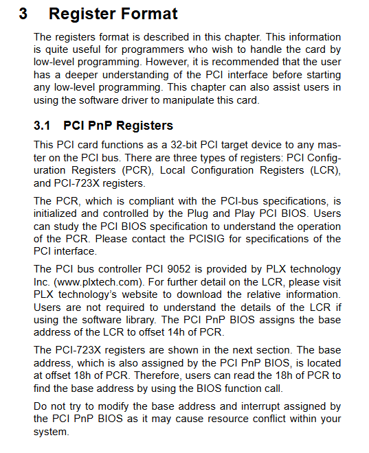
1. PCI Plug and Play Register Architecture
The board adopts PLX PCI9052 PCI controller and three types of registers:
PCR (PCI Configuration Register): The BIOS allocates the base address and interrupt number, and manual modification is prohibited to avoid resource conflicts;
LCR (Local Control Register): The underlying register of the PLX chip, which does not require operation when using official drivers;
723X card dedicated IO register: program reads and writes DI/DO data core.
2. IO address mapping (all 32-bit ports, prohibit 8/16 bit read and write)
PCI-7230: Base address 0~3, read=DI register, write=DO register;
PCI-7233: Base address 0-3, read-only DI (32 channels);
PCI-7234/34P: Base addresses 0-3, only write DO (32 channels).
3. Input/output register bit mapping
DI register: Base+0 corresponds to channels 0-7, Base+1 corresponds to channels 8-15, Base+2 corresponds to channels 16-23, and Base+3 corresponds to channels 24-31; Only 7233 uses high 16 bits;
DO register: The bit arrangement corresponds exactly to DI; Only the lower 16 bits of 7230 are valid, while all 32 bits of 7234/34P are available.
Working Principles of Circuits
1. Isolated digital input circuit (7230/7233)
Single ended input: External signals are protected by a 1.2k Ω current limiting resistor and bidirectional voltage regulator, isolated by optocoupler PC817, and converted to TTL level before being sent to the board logic; EICOM can be connected to external power supply ground or high potential, and supports NPN/PNP sensors;
Differential input (only cPCI/LPCI/LPCIe-7230): DI_nH and DI_nL differential signal input to suppress common mode interference;
2. Isolated digital output circuit (7230/7234/34P)
Commonality: An external VDD 5-35V DC power supply is required, with a built-in freewheeling diode on the board to protect inductive loads such as relays and solenoid valves; Optocoupler isolates the host side from the external load side;
PCI-7234 (Sink current): One end of the load is connected to VDD, and the other end is connected to IDO output, with current flowing into the board;
PCI-7234P (Source Pull Current): One end of the load is connected to IGND, and the other end is connected to IDO output, with current flowing out from the board;
Two typical wiring examples:
Output driven TTL input;
Output directly drives another acquisition card to isolate the input channel.
3. PCI-7233 COS jump detection and dual interrupts
COS definition: Input level changes at any edge (rising/falling); Real time detection of all hardware in 32 channels;
Dual interrupt logic: The hardware is divided into two groups of channels, 0~15 and 16~31, which independently trigger interrupt signals INT1/INT2 and share the same PCI interrupt IRQ;
Interrupt latch: The jump interrupt signal will be latched, and the interrupt flag must be cleared by calling the _7233_CLR-IRQ software function before the next jump can be received;
Timing: Each channel level change generates COS pulses, and all channel pulse logic outputs interrupt requests.
Chapter 1.5: Full Platform Software Support System (Core Development Ecology)
The document comprehensively summarizes Linghua’s third-generation drivers, supporting tools, and third-party software adaptation. It is recommended to prioritize the use of the new generation DAQPilot driver and eliminate traditional DASK.
1. Windows drivers (two major systems)
(1) The new generation DAQPilot (officially promoted)
Positioning: Task oriented unified driver SDK, universal for all series of DAQ cards;
Development interfaces: native APIs, ActiveX controls,. NET assemblies; Support ADE development environments such as VB.net/C #/VC++/Delphi/BCB;
DAQMaster: a graphical device manager with functions including hardware recognition, software management, DAQPilot task configuration, and DAQ-2000 series calibration;
Advantages: Reduce learning costs, quickly complete collection tasks, and adapt to Windows 98/2000/XP/Vista 32/64 bit systems.
(2) Traditional legacy DASK driver (compatible with old projects)
There are three types of kernel drivers (32-bit. sys kernel):
PCIS-DASK: compatible with NuDAQ PCI/cPCI/LPCIe series (used on this 723X board);
D2K-DASK: DAQ-2000/PXI-2000 analog acquisition card;
WD-DASK: High speed waveform digitizer;
Features: Supports Vista 64 bit digital signatures, WOW64 compatibility layer (32-bit programs run directly on 64 bit Windows without modification); The lower level IO operation has higher freedom, suitable for deep customization of lower level development.
2. Linux driver DASK/X
Linux port versions corresponding to Windows DASK: PCIS-DASK/X, D2K-DASK/X, WD-DASK/X, providing a unified cross platform API for customizing collection programs under Linux.
3. Complete adaptation of third-party software
MATLAB: DAQ-MTTLB toolkit, compatible with MATLAB data acquisition toolbox, Linghua is an official partner of MathWorks, supporting up to 65MHz high-speed digitizers;
LabVIEW: DAQ-LWIEW PnP Plug and Play VI Library, compatible with NI standard DAQ controls, providing four major tool panels: analog input/output, digital IO, and counter, supporting LabVIEW 6.5~8.5;
Agilent VEE: PICS-VEE (NuDAQ digital IO card, including 723X full series), D2K-VEE (2000 series analog card), visual process programming;
SCADA/HMI is equipped with DAQPench: a 32-bit ActiveX control library that provides trend charts, alarms, and UI components. It is used in conjunction with Tag servers and OPC servers to interface with PLCs and databases for industrial monitoring upper computers;
DAQCreator: an out of the box tool for data acquisition, display, FFT analysis, high-speed hard disk storage (40MB/s streaming drive), and high-speed logging with SCSI hardware.
Overall value and target audience of the document
Hardware engineer: board selection, anti-static installation, external wiring, terminal board matching, isolation circuit design reference;
Bottom layer driver development: complete PCI registers, 32-bit IO port mapping, COS interrupt hardware logic;
Upper computer software engineer: Windows/Linux driver selection, LabVIEW/MATLAB/VEE third-party development solutions, SCADA monitoring system setup;
Equipment maintenance personnel: hardware troubleshooting, after-sales form filling, driver software installation steps.
Summary of Supplementary Key Precautions
All DO channels must be connected to an external power supply VDD of 5-35V, and 5V from the PCI slot alone is insufficient to drive external loads;
Forcing 32-bit read and write of IO registers, 8/16 bit access will cause abnormal operation of the board;
LPCI/LPCIe-7230 isolation withstand voltage is only 2500V, and PCI/cPCI-7230 (5000Vrms) is preferred for industrial strong interference scenarios;
PCI-7233 interrupt must be cleared by software, otherwise it cannot capture the next level jump;
Inductive loads (relays, solenoid valves) cannot omit the continuous current circuit of the board to avoid damage to the drive chip;
Priority should be given to DAQPilot for new project development, while old historical programs can retain compatibility with DASK drivers.