ADLINK PCIe FIW Series 1394b Image Acquisition Card
Product Overview
1. Product positioning and model differentiation
PCIe FIW is an IEEE1394b high-speed image acquisition card based on PCIe bus, used to connect 800Mbps industrial FireWire cameras, divided into two types:
PCIe-FIW64:x4 PCIe, 4-channel 1394b industrial locking interface, integrating 4-channel isolated DI+4-channel isolated DO+4-channel isolated trigger input/output, complete machine vision synchronous control;
PCIe-FIW62:x1 PCIe, 2-channel 1394 industrial lock interface, no digital IO/trigger, only for image transmission;
2. Core universal features
Bus: FIW62 x1 PCIe; FIW64 x4 PCIe, Backward compatible with x8/x16 slots;
Transmission rate: Supports 100/200/400/800Mbps 1394b standard, compatible with 1394/1394a;
Interface: Industrial 9-pin 1394b interface with screw locking, anti loosening; The cable can provide power to the camera (Power over FireWire);
Status indicator light: Each channel has an independent green LED, which is on to indicate that the device is connected normally;
System support: Windows XP, XP Embedded, Vista;
3. Typical application scenarios
Industrial vision online inspection, scientific research instrument imaging, medical image acquisition.
Hardware reference (complete specifications, pins, and circuits of two types of hardware)
2.1 PCIe-FIW64 (high-end with isolated IO/trigger)
(1) Basic electrical and environmental parameters
Isolation withstand voltage: IO/trigger channel 1000V@60s Photoelectric isolation;
Size: 129.5mm × 111.15mm;
Temperature and humidity: working at 0-55 ℃, storage at 0-85 ℃, humidity at 5-90% without condensation;
Power consumption:+12V maximum 200mA,+3.3V maximum 2.5A;
(2) Instructions for onboard connectors
CN1~CN4: 4-channel 1394b camera interface (9-pin)
Differential TPA/TPB signals, VG power supply ground, VP cable power supply pins, matched with locking industrial connectors;
CN5: External 4pin 12V auxiliary power supply: High power cameras can be powered by an external 12V power supply;
SW1 dip switch: Card ID card number selection
4-speed dialing, up to 4 FIW64 cards can be installed in the system, and the card ID (0-3) can be defined through switches to distinguish between multiple card channel numbers;
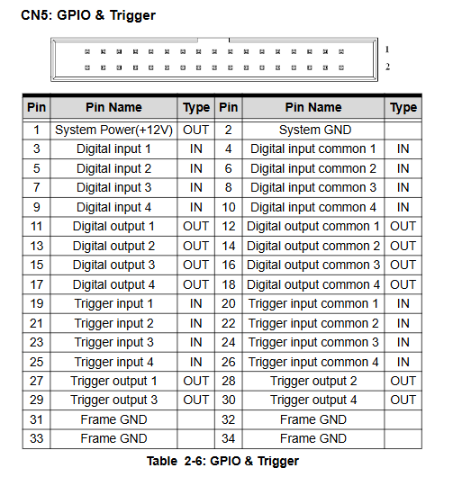
CN7:37 pin extended D-Sub terminal: leads out all DI/DO/trigger IO, convenient for external terminal block connection;
(3) Isolate IO and trigger hardware parameters
Universal digital DI (4-channel optoelectronic isolation)
Input voltage 0~25V; low level 0~0.5V, high level 2~25V;
Universal digital DO (4-channel optoelectronic isolation, current output)
Load range of 3~24V, maximum single channel current of 80mA, voltage drop ≤ 1V;
Isolation trigger input Trig IN (4 channels)
0~25V input, minimum trigger pulse 0.1ms, configurable rise/fall edge trigger;
Isolation trigger output Trig OUT (4-channel TTL)
Load 0-5V, maximum 40mA current, used for synchronous flicker and camera exposure;
(4) Programmable triggering core timing function (exclusive to FIW64)
Single trigger can independently configure three major parameters:
Trigger delay T2:0~1000ms, step 1ms; input edge delay before output trigger;
Trigger pulse width T3: 0.1~50ms, step 0.1ms; output pulse duration;
Trigger polarity (4 levels optional)
0: Input falling edge+output low effective;
1: Input falling edge+output high effectiveness;
2: Input rising edge+output low effective;
3: Input rising edge+output high effectiveness;
Busy inhibition mechanism
Ignore new input signals before triggering the output to avoid repeated triggering; Busy cycle=pulse width+0.1ms;
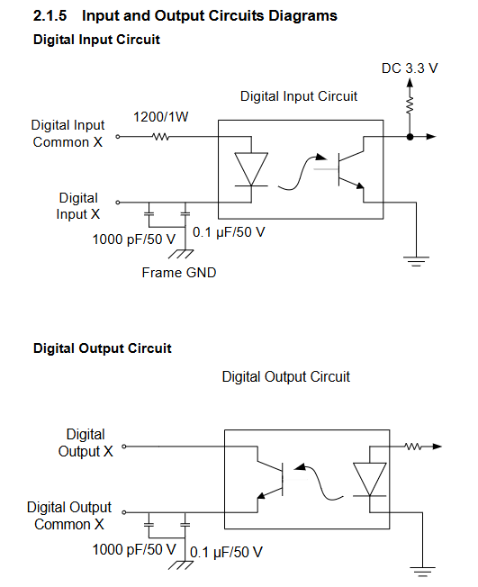
(5) Circuit and wiring examples
The complete document provides internal optocoupler schematics for DI, DO, and Trig IN/OUT, along with external wiring examples
Connect switch signals to DI, TTL device inputs, solenoid valve/indicator light DO control, strobe light trigger output, DI-DO loop self-test wiring diagram;
2.2 PCIe-FIW62 (Basic 2-channel imaging model, no IO)
Bus: x1 PCIe, size 78.6 × 105.75mm;
Interface: 2-channel locking 9-pin 1394b, two independent LED connections;
Hardware: Comes with 2kbit EEPROM, only for image transmission, without any digital IO/trigger circuits;
Power consumption:+3.3V, maximum 0.22A, also supports 4pin external 12V camera power supply.
Complete installation process of hardware and driver
3.1 Hardware installation steps
Power off the entire machine, open the chassis, and select an idle PCIe slot (FIW62: x1/x4/x8/x16; FIW64: x4/x8/x16);
Handheld card edge anti-static, smoothly insert and fix the baffle screw;
Connect the camera with a 1394 cable, and connect the high-power camera to an external CN5 12V auxiliary power supply;
Power on and start up.
3.2 Windows driver installation in two steps (FIW64 requires dual drivers)
Step 1: The system comes with a built-in 1394 OHCI low-level driver
XP/Vista comes with TI OHCI compatible 1394 controller driver;
When a yellow exclamation mark appears in the device manager, manually update the driver and select the standard OHCI IEEE1394 controller;
Step 2: FIW dedicated IO/trigger driver (only required for FIW64)
Run the disc FIW64_SetupDisk.exe and install the InstallShield wizard with just one click;
Vista Special Mandatory Settings
UAC user account control must be turned off and restarted, otherwise IO/trigger functionality will fail.
FIW64 API Library Development Manual
Only PCIe-FIW64 provides a C-style development API, divided into three categories: system functions, DIO functions, and trigger functions, with complete syntax, parameters, and error codes.
1. System basic functions (device enumeration, initialization)
FIW64Initialize: Initialize the driver, all programs must be called first;
FIW64_GetTotalDeviceNum: Read the total number of FIW64 in the system;
FIW64_GetTotalDeviceID: Read all card IDs (defined by dialing);
FIW64_SesetDevice: Single channel/All channel hardware reset;
FIW64_GetFirmwareVersion: Read the firmware version of the board;
FIW64_GetError Message: Error code to text prompt;
2. Universal digital IO functions
FIW64_SetDO: Set the high and low levels of a single digital output;
FIW64_GetDI: Read the isolated digital input status of a single channel;
3. Trigger the control core function (visual synchronization core)
FIW64_SetTriggerDelayTime/Get: Set/read trigger delay;
FIW64_SetTriggerWidth/Get: Set/read the output pulse width;
FIW64_SetTriggerPolarity/Get: Configure/Read Trigger Polarity (4 modes);
4. Global Error Code Comparison Table
0: No errors
-1: The device does not exist
-2: Driver loading failed
-3: The device cannot be opened
-4: Abnormal device access permissions
-5: Illegal channel number
-6: SPI hardware communication failure
-7: Parameter out of range
-8: Card ID dialing configuration error