ADLINK cPCI-3534/3544/3538 series CompactPCI serial port module
Overview of core differences across the entire series of models
1. Model Basic Specification Comparison Table
Model serial port configuration isolation feature interface output R suffix (later IO version) maximum number of cards per system/serial port matching cable
CPCI-3534 3-channel RS232+1-channel isolated RS422/485 D port independent 500VDC isolated DB37 front out support cPCI-R3534 backplane 2/8-port C425M (DB25), C409M (DB9)
CPCI-3544 4-channel fully isolated RS422/485 4-channel mutual isolation, hardware switching protocol DB37 front-end support cPCI-R3454 backplane 8/32 ports C425M, C409M
CPCI-3538 8-channel standard RS232 (no isolation) without isolation DB62 front out support cPCI-R3538 backplane 2/16 ports C825M (DB25), C809M (DB9)
General Hardware Fundamentals
Bus: 32-bit CompactPCI, PCI2.1 plug and play, BIOS automatically assigns IRQ and IO addresses
Serial port controller: compatible with 16C554, clock 1.8432~7.3728MHz, maximum baud rate 115200bps, single channel independent baud rate configuration
Electrical protection: Surge protection is built into the entire series; 3534/3544 differential channel 500VDC isolated withstand voltage
Physical dimensions: Unified 3U cPCI specification 160mm × 100mm, typical power supply+5V 1400mA
Environment: Working temperature range of 0-55 ℃, storage temperature range of -20~65 ℃, humidity range of 10%~95%, no condensation
Detailed Introduction to Three Board Modules
(1) CPCI-3534 (3RS232+1 isolated 422/485)
hardware architecture
A/B/C three channel standard RS232, complete modem signal (TX/RX/RTS/CTS/DSR/DSR/DDR/RI)
D channel independent isolation differential port, can switch RS422/RS485 through jumper, built-in terminal resistance jumper JP1/JP2
On board DIP dialing is used for multi card number recognition, distinguishing the starting number of COM ports
Interface Definition
Front board DB37 female seat, external DB25/DB9 male cable; The R version is connected to the cPCI J2 backplane for IO output
RS232 pin complete modulation and demodulation signal; D differential channel distinguishes TX+/-, RX+/- (422)/D+D – (485), independently isolated ground
The maximum limit for a single industrial computer in the system is 2, with a total of 8 serial ports
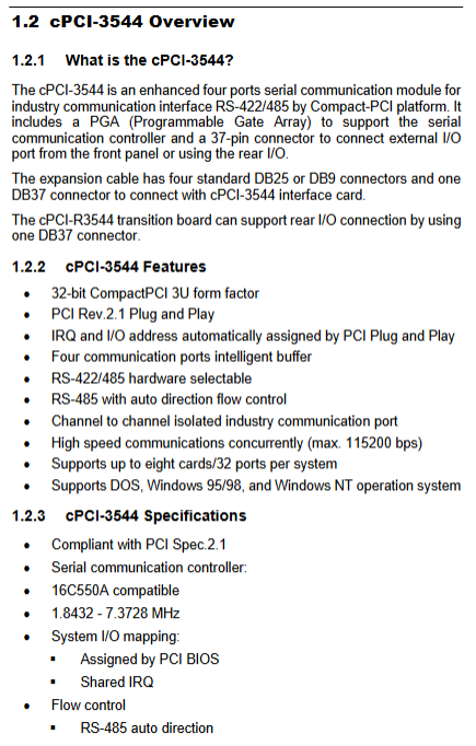
(2) CPCI-3544 (4-channel fully isolated RS422/485)
Core advantages
Four channels are electrically isolated from each other, with 500VDC isolation; DIP dialing selects RS422 or RS485 mode channel by channel
RS485 comes with hardware automatic flow control, eliminating the need for software to control transmission and reception switching
JP1~JP8 jumpers correspond to 4-channel 422/485 terminal resistors, and are connected to matching long line impedances as needed
SW1-3 three digit dialing setting board card number (0-7), with a maximum of 8 cards per system and a total of 32 differential serial ports
Interface DB37 front interface, R version J2 backplane rear IO; four differential channels share DB25/DB9 distribution cable, only differential signal without RS232 modulation signal
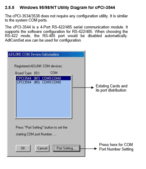
Supporting tool AdlComSet.exe for visual configuration of 422/485 working modes for each channel on Windows
(3) CPCI-3538 (8-channel standard RS232, no isolation)
hardware features
8 independent RS232 channels (A~H), all standard modem handshake signals, supporting Xon/Xoff, RTS/CTS hardware flow control
On board JP1 single jumper distinguishes between 1/2 cards, limiting the system to a maximum of 2 cards, totaling 16 RS232 channels
No isolation design, optional external C588XB expansion box to increase isolation function
DB62 high-density connector on the interface front board, matched with 8-port DB25 distribution cable; R version supports backplane rear IO
Applicable scenarios: Only short distance standard RS232 device networking, no need for differential anti-interference scenarios
R version rear IO supporting backplane
Corresponding models: cPCI-R3534/cPCI-R3544/cPCI-R3538, compatible with J2 cPCI backplane interfaces for three different cards
Function: Transfer the serial signal from the front board to the rear of the chassis without changing the pin definition or cable specifications, suitable for industrial control devices that are enclosed and have no wiring space in the front
Wiring standard: The rear connector, branch cable, and front outlet are fully compatible
Hardware dialing/jumper configuration rules
cPCI-3534
SW1-1: Card recognition jumper, ON=Card 1 (COM start number earlier), OFF=Card 2
JP1 (422 terminal), JP2 (485 terminal): Short circuit enable 120 Ω matching resistor
cPCI-3544
SW1-3 three digit dialing: Set board ID 0-7 to distinguish between multi card COM segments
JP1/JP3/JP5/JP7 (422 terminal), JP2/JP4/JP6/JP8 (485) four-way independent terminal jumper
cPCI-3538
JP1: ON=first card, OFF=second card, only supports dual card system
General rule: Multi card systems must stagger dialing, otherwise COM port conflicts and communication abnormalities may occur
Complete installation process
1. Anti static code for unpacking
Full process anti-static wristband+anti-static pad, touch only the edge of the board, do not touch the chip pins
Before receiving the goods, check for transportation damage and confirm that the IC socket is not loose by pressing it; Damage is strictly prohibited from being powered on
2. Hardware installation steps
Turn off all power to the entire machine and peripherals
The human body releases static electricity, and the edge of the handheld card is inserted into an idle 3U cPCI slot
Screw fixed panel; Pre set corresponding dialing codes for multiple cards to distinguish card numbers
Connect the DB distribution cable to the front panel DB37/DB62 or the rear panel
3. Software driver installation (supported across all platforms)
Supporting operating systems
DOS、Windows3.1/95/98/NT/2000/XP、Linux、QNX、SCO Open Server
Windows NT installation process
The administrator account enters the control panel – Network Adapter, selects “Manufacturer Disk”
Read the CD drive directory for the corresponding model and customize the COM starting number (default starting from COM3)
Dual SIM requires one DIP ON and one OFF, which will take effect upon restart; Uninstall the old driver before reinstalling it
Windows 95/98 plug and play
Automatically recognize hardware upon startup, specify the driver path according to the instructions, and dial the code to determine the order of COM ports
Linux driver
Extract the source code package, compile and install the kernel module, and specify the number of installation cards with command-line parameters
CPCI-3544 dedicated configuration tool AdlComSet.exe
Visualize the interface to read all 3544 cards in the system, switch RS422/485 modes channel by channel, and select the option to save configuration when turned on
Definition and Explanation of Interface Pins
RS232 standard signal TX transmission, RX reception, RTS/CTS hardware flow control, DSR/DTR/DCD/RI modulation and demodulation signals, SG signal ground, FG chassis ground
RS422 differential TX+, TX -, RX+, RX -, independently isolated ground, point-to-point communication
RS485 differential D+, D – half duplex bus, hardware automatic transmission and reception switching, supports multi node bus networking
Split cable specifications: DB25 (full signal) and DB9 (simplified serial port standard) two types of male outlet cables