ADLINK DIN-814P-A4 4-axis dedicated motion terminal board
Basic Information
Product model: DIN-814P-A4, 4-axis dedicated sports terminal board
Hard adaptation restrictions
Only compatible with Linghua Sports Card: PCI-8134/PCI-8164/PXI-8164/MPC-8164/PCI-8158;
Only compatible with Panasonic MINAS A4 series pulse servo, while supporting stepper drivers; Prohibit pairing with servo systems from other brands such as Yaskawa, Mitsubishi, Delta, etc;
Core features: Specially customized for Panasonic A4 servo, supporting 500Kpps/2Mpps dual pulse rate switching, integrated servo exclusive torque/speed monitoring, electromagnetic brake, electronic gear interface, with each axis status indicator light, standard DIN rail installation.
Overview of Hardware Interfaces for the Whole Machine
Interface List and Functions
Specification and purpose of identification
CN2 100 pin SCSI-II bus one-to-one SCSI cable connects to Linghua 4-axis motion control card, transmitting all pulse, encoder, servo IO signals
CN1 2-pin terminal external DC24V ± 5% isolated power supply, providing EX+24V and EXGND isolated power supply ground
CNIF1~CNIF4 50 pin D-Sub Panasonic A4 servo dedicated main interface, dual rate pulse, torque/speed command, brake, electronic gear, encoder full function pins
SJ1~SJ4 10 pin row stepper motor simplifies pulse interface, only pulse/direction/enable/alarm/Z index
IOIF1~IOIF4 9-pin needle set with mechanical limit, origin, acceleration/deceleration, external reset isolation input for each axis
BH1~BH4 expand spare ports and reuse Panasonic servo dedicated monitoring/brake pins to expand advanced functions
JP1~JP4 4-bit jumper (independent for each axis) switching pulse output rate: 500Kpps/2Mpps
The LED indicator light group is matched with real-time display of PEL positive limit, MEL negative limit, and ORG origin sensor level for each axis
Mandatory wiring rules
The internal signals of the CNIF Panasonic servo port and SJ step inlet on the same axis can only be short circuited, and only one of the two wiring options can be used simultaneously; Panasonic servo must be paired with Linghua’s original 50 pin one-to-one dedicated cable.
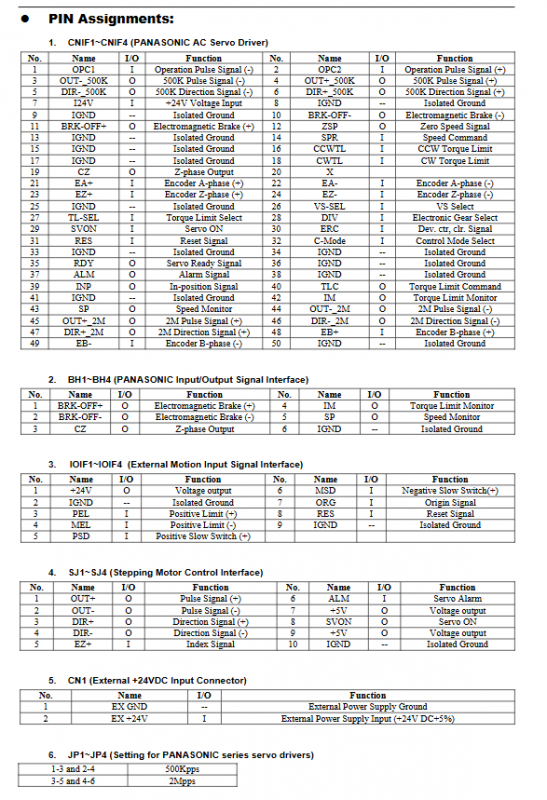
Complete pin definitions for each interface
1. CNIF1~CNIF4 (Panasonic A4 servo 50 pin core interface, core differentiated dual pulse)
Panasonic exclusive dual pulse channel, distinguishing between low-speed 500K and high-speed 2M differential pulses:
Pulse signal: OUT ± _500K, DIR ± _500K (500Kpps); OUT ± 2M, DIR ± 2M (2Mpps), switch output through JP jumper;
Encoder circuit: EA/EB/EZ three-phase differential feedback;
Servo enablement and control: SVON servo on, ERC error reset, RES driver reset, C-Mode control mode selection, DIV electronic gear switching;
Torque/speed control: CWTL clockwise torque limit, CCW counterclockwise torque limit, SPR speed command, TLC torque command, SP speed monitoring, IM torque monitoring;
Motor holding brake: BRK-OFF+/BRK-OFF – differential output of electromagnetic brake;
Servo status feedback: RDY servo ready, ALM alarm, IN positioning completed, ZSP zero speed detection;
External hardware: VS-SEL speed selection, TL-SEL torque selection, OPC external pulse input;
Power supply and isolation: I24V input, multiple independent IGND isolated ground.
2. JP1~JP4 pulse rate jumper (independent for each axis)
Short circuit 1-3, 2-4: Enable 500Kpps pulse channel (OUT ± 500K, DIR ± 500K);
Short circuit 3-5, 4-6: Enable 2Mpps high-speed pulse channel (OUT ± 2M, DIR ± 2M).
3. IOIF1~IOIF4 mechanical limit IO
Pin:+24V isolated output, IGND isolated ground, PEL positive limit, MEL negative limit, PSD forward deceleration, MSD reverse deceleration, ORG origin, external reset RES.
PSD pin function differentiation
PCI-8134: Forward deceleration switch only;
PCI-8164/PXI-8164/MPC-8164: Axis 1/2 PSD corresponds to CMP position comparison, and Axis 3/4 PSD corresponds to LTC latch signal.
4. SJ1~SJ4 stepper driver interface
Differential pulse OUT ±, differential direction DIR ±, EZ Z-phase index, ALM alarm, SVON servo enable, two-way+5V output, IGND isolated ground; No dedicated servo pins for simulating torque/speed, brake, etc.
5. BH1~BH4 expansion spare port
Reuse Panasonic exclusive monitoring pins such as BRK-OFF brake, Z-phase CZ, speed SP, torque IM, etc., to expand advanced servo functions. Conventional control does not require wiring.
6. CN1 power supply terminal
EX+24V (24V input), EXGND (isolated ground), providing isolated driving power for all external sensors and servo IO.
Hardware Isolation Circuit Description
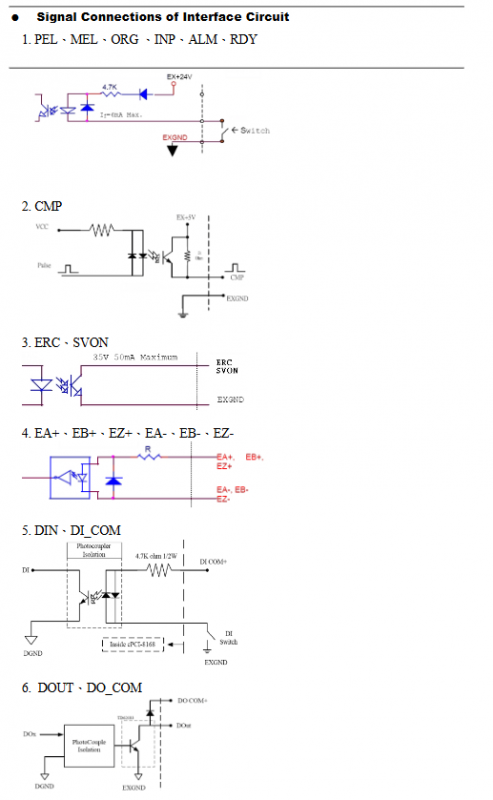
The document provides a complete set of optocoupler isolation schematics, with all external IO, pulse, and encoder signals isolated to suppress industrial EMI and ground loop interference:
Limit/origin/alarm DI circuit: 4.7K pull-up resistor, maximum input current 6mA, compatible with NPN/PNP photoelectric switches;
SVON/ERC digital output optocoupler isolated driver;
High speed pulse, position comparison CMP dedicated optocoupler circuit;
High speed HSIN/HSOUT high-speed input/output isolation circuit, suitable for high-speed pulse scenarios.
Overall wiring topology of the system
Linghua motion control card (100 pin SCSI cable) → DIN-814P-A4 terminal block → 50 pin dedicated cable → Panasonic MINAS A4 servo; The stepper motor is directly connected to the SJ pin without the need for a 50 pin cable.
Mechanical dimensions
Standard 35mm DIN rail installation, overall panel size 123mm × 107mm, complete 2D structural drawing attached, reserved fixing screw holes on both sides, compatible with standard electrical control cabinets.
Horizontal comparison of specialized terminal boards in the same series
DIN-812M: 2-axis, only compatible with PCI-8132, Mitsubishi J2S specific;
DIN-814Y: 4-axis, exclusively for Yaskawa servo;
DIN-814M-J3A: 4-axis, Mitsubishi J3A servo specific;
DIN-814P-A4: 4-axis, Panasonic MINAS A4 servo exclusive, unique 500K/2M dual pulse rate jumper;
DIN-814-GP: 4-axis universal, compatible with all brands of servos, without dedicated servo analog control pins.