ADLINK MXA-200 Industrial IoT Energy Gateway
Product Introduction
1.1 Product positioning
MXA-200 is an industrial grade energy IoT gateway, with the core functions of multi protocol Ethernet/serial data conversion, device networking, and cloud data uploading; Applicable scenarios: energy consumption monitoring, charging pile control, new energy generation monitoring, intelligent manufacturing.
Adopting the NXP i.MX8M Plus quad core platform and a wide temperature fanless industrial design, it supports the expansion of Wi Fi/4G/5G wireless modules and is aimed at industry integrators who require massive data collection, cloud services, and video surveillance.
1.2 Core Hardware Features
Processor: NXP i.MX8M Plus 4 × Cortex-A53 1.8GHz, integrated M7 coprocessor
Storage: 2/4GB LPDDR4 memory, 32/64GB eMMC local storage, with microSD expansion slot, TPM2.0 security chip, RTC clock (monthly error ≤ 180 seconds), hardware watchdog
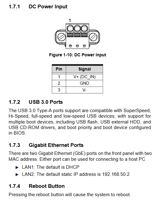
Network port: 2 Gigabit RJ45 Ethernet (default DHCP for LAN1, static 192.168.50.2 for LAN2)
Serial port: 2-way isolated 4-wire RS-232/422/485 (COM1/COM2 factory default RS485 9600, N, 8,1)
USB: 2-channel USB 3.0 Type-A; 1 Micro USB debugging port
Display: HDMI video output
Expansion slot: M.2 E-Key (Wi Fi/Bluetooth) M.2 B‑Key(4G/5G LTE)
Wireless antenna: 6-way SMA antenna interface (ANT1~ANT6), microSIM card slot (dedicated for cellular modules)
Machinery and Environment
Size: 110.90 (L) × 40 (W) × 131.40 (H) mm, all metal fanless body
Installation method: Standard DIN rail installation kit, wall mounting kit
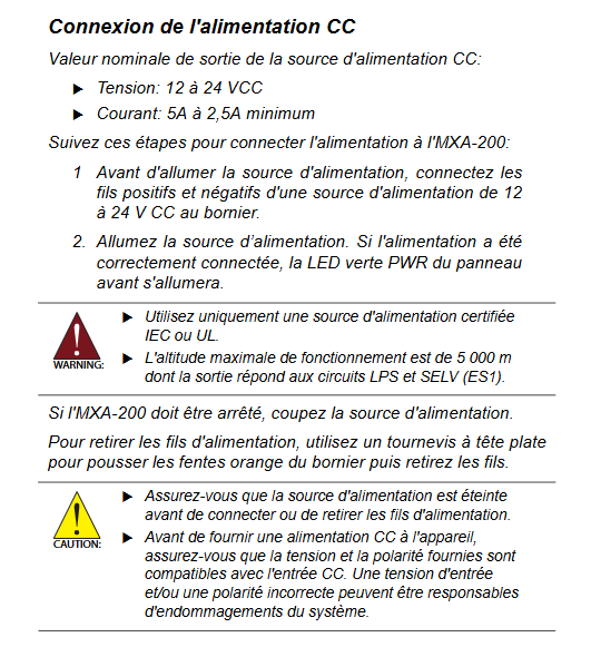
Power supply: 12-24V DC input, minimum current 2.5A (24V)~5A (12V)
Temperature and humidity: working -20 ℃~70 ℃, storage -25 ℃~80 ℃; 95% non condensing humidity at 40 ℃
Anti vibration and anti impact: Complies with IEC industrial vibration/impact standards, X/Y/Z triaxial testing
Certification: CE, UKCA, RCM, KC, FCC; Industrial EMC, UL/CSA/IEC 62368-1, 61010 series certification
1.3 Packaging List and Optional Accessories
Factory standard: MXA-200 host, DIN rail fasteners (2 flat head screws), wall bracket (4 pan head screws), quick start guide
Optional accessories: 24V/90W power adapter (part number 31-62187-1000-A0)
1.4 Full definition of I/O interfaces
Front interface (power supply, network port, USB, buttons, antenna)
A: DC power terminals (V+, GND, V -); F: Grounding screw; B: Dual USB 3.0
C/D: Dual Gigabit Ethernet ports; E: Function reset button (long press to restore factory)
G/H/I: ANT1/2/3 antenna pedestal; Indicator lights: PWR power light, WLAN wireless LAN light, WLAN cellular light, PGM firmware burning light
Side interface (serial port, HDMI, SIM/SD, remaining antenna)
J: Micro USB debugging; K:HDMI; L/M: COM1/COM2 5-pin serial port terminal
N: MicroSD+SIM composite slot; O/P/Q: ANT4/5/6 antenna mount
Serial port pin definition (single 5pin terminal, compatible with 3 modes)
RS232:1=CTS、2=RX、3=TX、4=RTS、5=GND
RS422:1=TXD‑、2=TXD+、3=RXD+、4=RXD‑、5=GND
RS485: 1=DATA -, 2=DATA+, 5=GND (3/4 empty)
Function keys restore factory default parameters
Login account: root, password: adlink
LAN1 automatically obtains the IP, LAN2 is fixed at 192.168.50.2; Unified serial port RS485 9600; Clear Wi Fi/cellular network configuration
1.5 Mechanical drawings
The document provides a complete set of three views, dimension annotations, two installation schemes for DIN rails, and three installation schemes for wall mounting, including screw torque, hole size, and bracket assembly diagram.
1.6 Hardware Function Block Diagram
Display i.MX8M Plus main control and power supply, Ethernet PHY, serial transceiver, USB Hub, M.2 expansion TPM、RTC、HDMI、 The complete signal link of antenna RF.
Quick to get started (unboxing and powering on)
Open box inspection: Check for damaged outer packaging and missing accessories. Contact the dealer; Returns require prior authorization from the manufacturer and retention of packaging materials.
Wiring steps for DC power supply
In the power-off state, connect the positive and negative terminals of the 12-24V power supply to terminal V+/V -; The terminal requires a straight screwdriver to press the orange buckle to disassemble the wire, with a wire specification of 16-24AWG copper core wire.
After power on, the green PWR light stays on, indicating normal power supply; Only UL/IEC certified LPS/SELV safety power supply is used, with a maximum working altitude of 5000 meters.
Shutdown method: Cut off the DC power directly and do not hot plug the terminals.
Appendix A: Configuration of the Debian Linux Operating System (System Operating Core)
The device comes pre installed with Debian Linux and is designed for secondary development integrators, covering hardware debugging, network, serial port, and wireless module configuration
A. 1. Hardware basic deployment
LAN2 (static 192.168.50.2) is used for local SSH debugging, while LAN1 is connected to the external network; Connect to 12-24V DC for automatic startup.
A. 2 SSH remote login (most commonly used debugging method)
Set the PC network segment to 192.168.50.xx, select SSH for Putty, address 192.168.50.2, port 22
Account root, password adlink; After logging in, obtain the aarch64 Debian terminal
A. 3 LED indicator logic
PWR: Always on when powered on; WLAN: lights up after installing Wi Fi module system startup; After loading the 4G/5G module, it lights up; PGM: Lights up when burning firmware to SD card.
A. 4 Serial port mode switching command
Query COM1/2 mode: cat/sys/class/gpio_Switch/com1Mode
Switching protocol: echo RS232/RS422/RS485 to write to the corresponding node; Serial device node: COM1=/dev/ttymxc2, COM2=/dev/ttymxc3
A. 5-port configuration file
LAN1 (eth0) configuration file:/etc/systemd/network/10-eth.network.exe
LAN2 (eth1) configuration file:/etc/systemd/network/11-eth1.network.exe, modified using vi editor
A. 6 4G/5G cellular module configuration (nmcli tool)
Complete process: Check the status of the network card → Create a new cellular connection → Activate the connection → Check the IP address of the WWAN0 network card → Ping the external network test → Disconnect the connection; Supports multiple industrial modules including Quectel, Sierra, and Telit, requiring the insertion of a microSIM card.
A. 7 Wi Fi wireless configuration
The nmcli command directly connects to the AP in the format of nmcli dev wifi connect “SSID” password “password”; successfully generates the wlan0 wireless network card, and can specify the network card to ping the public DNS to verify connectivity.
Appendix B Hardware Disassembly and Assembly of Wireless Module (Wi Fi/4G/5G)
The disassembly and assembly process of the three types of modules is unified: remove the 8 screws of the chassis to open the cover → remove the corresponding antenna hole cover → insert the SMA RF cable and lock nut (torque 6-8kgf. cm) → install the M.2 module and fix the copper column (4-5kgf. cm) → connect the RF cable to the antenna base according to the corresponding wiring diagram → install the thermal conductive aluminum block (tear off the double-sided release paper, torque 3.5-4kgf. cm) → restore the top cover.
The document provides three types of module specific RF wiring diagrams, distinguishing the antenna allocation schemes for different manufacturers’ modules (Sierra EM7421, Quectel EM05-G, Telit MV32-W-AD).
Safety regulations
General safety requirements
The recommended working environment for the equipment is 5-50 ℃, and it should be installed in a computer room that meets national standards as a priority; Before disassembly, the power must be turned off, and all chassis covers must be restored before powering on.
Protection requirements: Keep away from liquids, high temperatures, and enclosed environments without ventilation; The power supply circuit must be grounded; Long term idle power outage.
Danger warning: The body is running at high temperatures and should be touched after cooling down; Built in lithium battery, there is a risk of explosion if the wrong model is replaced, and the waste battery is recycled in compliance.
Maintenance restriction: Only authorized engineers are allowed to dismantle and repair the machine. If there is water ingress, falling, or wire damage, it must be returned to the factory.
Electrical Installation Specification
Tightening of power terminal wires, control of access permissions to the computer room (only licensed operation and maintenance personnel can operate), and providing bilingual English and French security terms.