ADLINK MXE-310 Series Rugged and Compact edge computing Device
Product Introduction
MXE-310 is an all aluminum alloy shell industrial embedded platform that uses Intel’s 13th generation Core i3/i5/i7 processors. It is designed for harsh industrial environments and features rich native IO and 3 independent M.2 expansion slots, which can be used to expand wireless, cellular, and storage modules.
1. Packing list
MXE-310 host, wall bracket, DIN rail and storage fixing screws, quick start guide.
2. Choose accessories
120W AC-DC power adapter (model 31-62163-1010-A0); Firmware, drivers, and BIOS can be downloaded from the official website of Linghua.
3. Core hardware features
Size: 180 (W) × 130 (D) × 70 (H) mm;
Memory: Dual channel DDR5 SO-DIMM 4800MHz, maximum 64GB;
Display: HDMI 2.1, DP 1.4a, USB-C (supports DP output, 5V3A power supply);
Serial port: 4 COM ports, COM1/2 supports RS232/422/485, COM3/4 only supports RS232;
Network port: LAN1 (Intel I219-V Gigabit); LAN2 (Intel I225-V, 2.5G Gigabit);
DIO: 8-way DI, 8-way DO;
Expansion slots: M.2 M-Key (NVMe storage), M.2 E-Key (WiFi), M.2 B-Key (4G/5G cellular with SIM card slot);
Audio: Realtek ALC888S, line input, output, microphone input;
Protection: 30G shock resistance, 3Grms vibration resistance, optional wide temperature version; Onboard fTPM2.0.
Detailed specification parameters
1. System and IO
The CPU is divided into two power consumption levels: 15W and 28W; Equipped with 1 SATA 6Gb/s interface; USB includes 2 x USB 3.2 Gen2 and 3 x USB 2.0.
2. Power consumption
Table
CPU gear shutdown system idle CPU full load machine full load recommended minimum power supply
15W 3.9W 14.5W 24.3W 31.3W 60W
28W 3.9W 15W 39.3W 46.6W 60W
Note: Power consumption is only used for power planning, actual power consumption depends on the application scenario.
3. Environmental conditions
Power supply: 12-24V DC;
Working temperature: -20 ℃~+60 ℃; Storage temperature -40 ℃~85 ℃;
Humidity: operates at 10-85% without condensation; Store 10-95% without condensation;
4. Authentication and Operating System
Certification: CE/FCC Class B, CB, UL/cUL safety certification;
Supported systems: Windows 10 IoT Enterprise LTSC21H2 64 bit Ubuntu22.04。
Quick Installation Chapter
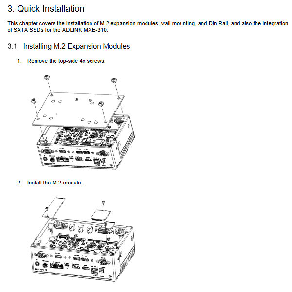
M. Module installation: Remove the top 4 screws, install the M.2 module, and reinstall the heat dissipation top cover locking screws.
Wall mounted installation: Use matching M4 screws to fix the wall bracket; Heat dissipation reminder: The CPU/PCH is located on the left side of the device, and a minimum 5cm heat dissipation gap is required below the device.
DIN rail installation: optional DIN rail, fixed with M4 screws; When using DIN rails, the machine’s vibration resistance is reduced to 1G.
SATA SSD installation: Remove the top cover, secure the SSD, and connect the SATA data cable to the power supply.
Mechanical layout
Definition of onboard connectors: M.2 M-Key, eDP/LVDS, FM board FPC interface, M.2 E-Key, M.2 B-Key, Nano SIM card slot, SATA power supply, SATA data interface.
Provide multi view engineering drawings: top, front, right, left, rear, and bottom views, including antenna interface positions (ANT1-ANT6) and overall dimensions of the machine.
Connectors and jumpers
1. Panel IO interface
Power button and LED: non self locking button; Power LED status: Always on when turned on, flashing in suspend/sleep mode, and turned off when turned off.
Ethernet port LED: LAN1 is gigabit; LAN2 supports 2.5G and defines the color and status of link/activity lights and rate lights respectively.
Three status LEDs on the panel: hard drive activity red light, diagnostic light (storage/memory failure), and user-defined light.
Video interface: DP1.4a, maximum 4096 × 2160@60Hz Complete pin definition.
USB interface: supports USB boot; It is recommended to perform a cold start when reinstalling the system using a USB drive.
DB9 serial port: COM1/2 can switch RS232/422/485 in BIOS; COM3/4 fixed RS232; Provide a serial port pin signal table.
DC power interface: 12-24V DC, interface size defined.
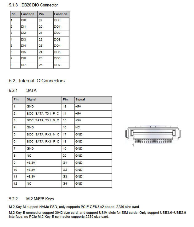
DB26 DIO interface: Fully define each pin of 8DI and 8DO.
2. Onboard internal connectors
Definition of SATA interface pins;
M. 2 Key specifications:
M‑Key:2280,NVMe SSD,PCIe Gen3 x2;
E-Key: 2230, WiFi module;
B‑Key:3042, Only USB bus, used for cellular modules, paired with Nano SIM card holder;
AFM expansion connector: used for customized functional boards of Linghua, leading out PCIe Gen4 × 4 USB3.0、SMBus、LPC;
RTC battery socket: connected to CR2032 3V button battery, used for system clock.
BIOS Settings (AMI EFI BIOS, press Delete to enter the settings interface)
BIOS is divided into seven menus: Main, Advanced, Chipset, Security, Boot, Save&Exit, MEBx
Main menu: Set system date and time.
Advanced Menu
CPU configuration: Hyper threading, enabling both large and small cores, virtualization VT-X, SpeedStep, C-State power management;
Power management: ATX/AT power mode, system status after power failure and restoration, RTC timed wake-up, PCIe wake-up;
Serial port redirection: Serial port console, baud rate, parity, flow control and other parameters;
USB configuration: storage device support, timeout parameters;
TPM 2.0 configuration: Enable security devices, PCR banking, TPM clearing, hierarchical control;
Onboard equipment: Set the COM port working mode and switch the network port;
BIOS watchdog: supports second/minute mode watchdog;
Network stack: PXE network boot (IPv4/IPv6).
Chipset chipset menu: System agent SA settings (memory, graphics card, VT-d), PCH IO, SATA/NVMe controller configuration.
Security menu: Administrator/User Password, Secure Boot Secure Boot, BIOS Lock.
Boot startup menu: Startup timeout NumLock、 Quick start and boot sequence settings.
Save&Exit: Save/discard modifications, restore defaults, call EFI Shell.
MEBx: Intel ME password, AMT switch.