ADLINK PCI-725X Series Relay Output and Isolation Digital Input Board
Product model and hardware characteristics
Model differentiation
Model Relay Isolation DI Remarks
PCI-7250 8-way (R0-R3 Form-C conversion; R4-R7 Form-A normally open) 8-way DI main card, onboard relay status LED indicator, DB-37 interface
PCI-7251 8-way 8-way DI expansion board, with a maximum of 3 7251s per main card, and a maximum of 32 relays+32 DI
CPCI-7252 8-channel all Form-C 16 channel DI CompactPCI industrial control computer backplane, 50 pin interface
LPCI-7250 8-Channel All Form-C 8-Channel DI Low Profile Short PCI Board
LPCIe-7250 8-way Form C 8-way DI PCI Express x1 bus
Form-C: COM, NO, NC (common, normally open, normally closed); Form-A: Only COM and NO, disconnected by default when powered on.
Core hardware specifications
Isolation digital input DI
Optocoupler chip: PCI-7250/7251/cPCI-7252 using PC-814; LPCI/LPCIe-7250 uses PC3H4;
Isolation withstand voltage: PCI-7250/51/cPCI-7252 is 5000Vrms; LPCI/LPCIe-7250 is 2500Vrms;
Input supports AC/DC signal: 5-24VAC/DC; Logic low 0-1.5V, logic high 5-24V; rated input current 10mA, maximum 60mA; input impedance 2.2k Ω;
JP1-JP8 jumper: Each channel independently selects DC unfiltered (default)/AC filtered input; Differential non-polar input, not positive or negative.
relay output
Contact specifications: resistive load 120VAC@0.5A ; 24VDC@1A ; 60VDC@0.3A The inductive load must be reduced in rating;
Mechanical lifespan: 1A@30VDC The condition is greater than 5 × 10 ⁵ times;
All relay coils lose power when powered on: the COM-NC of Form-C is connected, and all Form-A are disconnected;
Support reading back the actual status of the relay, not just writing back the register value.
Electrical and Environmental
Working temperature: 0-60 ℃; Storage -20-80 ℃;
Power consumption (all relays disconnected): PCI-7250+ 5V@140mA ;LPCIe‑7250 + 3.3V@280mA The+ 12V@180mA .
interface
PCI‑7250/7251:DB‑37 D‑Sub;
CPCI-7252, LPCI-7250, LPCIe-7250:50 pin SCSI II connectors.
Packing, hardware installation, and jumper cables
1. Packing list
Board body, driver CD, user manual, software installation guide; OEM version accessories may change.
Static sensitive devices must be operated with anti-static wristbands and anti-static pads.
2. DI input jumper settings (PCI-7250/51/LPCI-7250/LPCIe-7250)
JP1~JP8 correspond to DI0-DI7 channels one by one:
2-3 Short circuit: Non AC Filter, DC input (factory default);
1-2 Short circuit: AC-Filter, AC signal input, built-in filter of about 5ms.
3. Hardware installation process
Turn off the PC power and release human static electricity;
Set board jumper; Insert the corresponding PCI/cPCI/PCIe slot and secure the baffle with screws;
PCI plug and play, BIOS automatically assigns IO base addresses, and manual modification of resources is prohibited;
Windows recognizes new hardware upon startup and installs drivers.
4. PCI-7251 Expansion Board
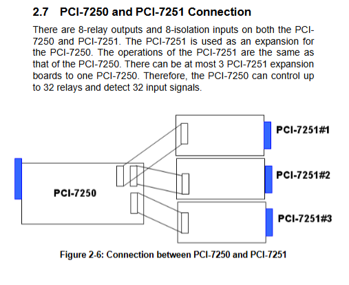
The CN2-CN4 socket on the PCI-7250 main card board can accommodate up to 3 external PCI-7251 expansion boards; The total scale after expansion is 32 relays and 32 isolated DIs. The expansion board does not have PCI gold fingers and only relies on ribbon cables to communicate with the main card.
5. Definition of connector pins
PCI-7250 DB-37: Each relay leads out COM, NO, NC; DI is differential DIx_H, DIx_L, and has no polarity.
CPCI-7252/LPCI/LPCIe-7250:50pin interface, differential DI, all relays COM/NO/NC.

Register underlying IO mapping
The board uses PLX PCI-9050 bridge chip, and all registers are 8-bit. Allocate IO base address by PCI BIOS.
PCI-7250 (with up to 3 7251 extensions)
Offset write read
0 relay output control byte relay readback status (main card)
1. Reserve isolated DI input bytes (main card)
Relay output control byte relay readback (# 1 expansion board)
3. Retain DI (# 1 expansion board)
4 Relay Output Control Byte Relay Read Back (# 2 Expansion Board)
5. Retain DI (# 2 expansion board)
6 Relay Output Control Byte Relay Read Back (# 3 Expansion Board)
7 Keep DI (# 3 expansion board)
Bit=1: Relay coil is energized, NO is closed; Bit=0: Power loss.
The DI register bit=1 indicates that the input is at a high level.
CPCI-7252, LPCI-7250/LPCIe-7250 use simplified register mapping, and the manual provides corresponding offset tables.
Working principle
relay output
Set the register bit to 1 and energize the coil; Set the bit to 0 and power off the coil;
It can read back registers to obtain the true relay status of hardware, not just software output values.
Power on reset, all bits are set to 0, and all relays are released.
Isolation digital input DI
Differential optocoupler input, does not distinguish signal polarity; Internal 2.2k current limiting resistor.
If external signals higher than 24V need to be connected, the upper limit current resistor Ri of the board needs to be replaced by oneself. The calculation formula is Ri=Vin/0.01A, and the resistor power needs to be calculated at the same time.
After the AC filter jumper is enabled, hardware filtering takes about 5ms to remove AC noise.
Appendix – Relay Inductive Load Protection Circuit (Key Engineering Tips)
Inductive loads such as relay drive coils and solenoid valves can generate reverse high voltage and burn out contacts when disconnected. The manual provides four protection schemes:
RC impedance capacitance absorption: both AC and DC can be used; RC is connected in parallel at both ends of the load. Selection: R takes 0.5-1 Ω per 1V voltage; C takes 0.5-1 μ F per 1A current.
Diode freewheeling: only suitable for DC loads; Reverse parallel inductive load with diodes; Reverse withstand voltage ≥ 10 times the power supply voltage. The disadvantage is that it will prolong the release time of the coil.
Diode+Zener combination: DC, solves the problem of slow diode release, and the Zener voltage is approximately equal to the supply voltage.
Varistor: AC/DC universal, parallel load at both ends.
Tip: There may be weak leakage current in RC circuits, and small current loads may cause misoperation.
Complete software driver and third-party support
Driver classification
DAQPilot (Next Generation Recommendation): Task oriented API; Provide ActiveX and. NET Assembly; Supporting DAQMaster configuration management tool, graphical browsing of boards and management tasks.
Traditional DASK driver kit
PCIS-DASK: PCI/cPCI series Windows kernel drivers;
PCIS-DASK/X: Linux version driver;
Third party software interface
LabVIEW:DAQ‑LVIEW PnP, Provide VI library;
MATLAB: DAQ-MTLB Toolbox;
Agilent VEE:PCIS‑VEE;
ActiveX component: DAQBench, used for SCADA/HMI configuration development;
DAQCreator: Ready to use data acquisition and recording software.
Supporting operating systems: Windows 98/NT/2000/XP/Vista (32/64 bit) Linux。
Typical application scenarios
The complete acquisition and control system consists of industrial switch ON/OFF control, external high-power relay drive, limit switch status acquisition, laboratory automation, and analog board combination.