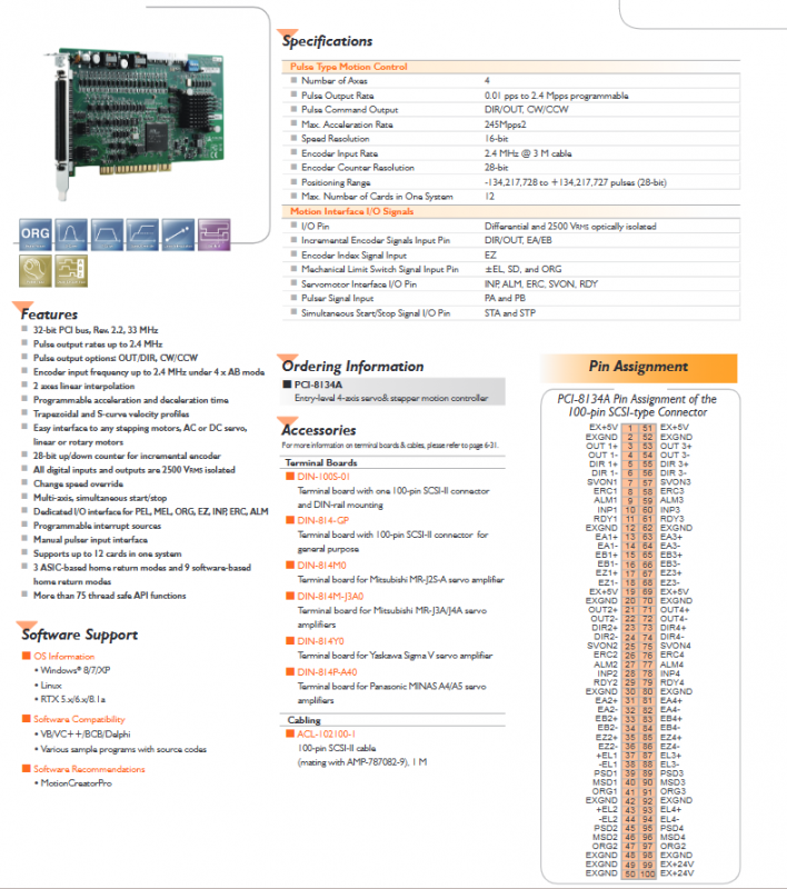
ADLINK PCI-8134A entry-level 4-axis pulse servo/stepper motion control card
PCI-8134A is an entry-level 4-axis pulse servo/stepper motion control card from ADLINK. Based on the PCI bus, it outputs control motors in a pulse train manner and can control stepper motors, AC/DC servo motors, linear/rotary motors. The entire set includes hardware features, electrical specifications, software support, optional accessories, connector pin definitions, etc. The document was updated on January 29, 2013.
Main hardware features
Bus: 32-bit PCI bus Rev. 2.2, clock 33MHz.
Pulse output: maximum pulse output rate of 2.4 MHz; Supports two pulse output modes: OUT/DIR pulse direction and CW/CCW dual pulse.
Encoder interface: In 4x AB decoding mode, the encoder input can reach up to 2.4MHz; Equipped with a 28 bit up and down counter to receive incremental encoder signals.
Interpolation and motion curve: supports 2-axis linear interpolation; Programmable acceleration and deceleration time; Support trapezoidal speed curve and S-curve speed profile.
Limit and origin related: dedicated IO interface connected to positive limit PEL, negative limit MEL, origin ORG, encoder zero phase EZ, servo in place INP, reset ERC, alarm ALM; Provide 3 ASIC hardware zeroing modes and 9 software zeroing modes.
IO isolation: All digital inputs and outputs have 2500 VRMS optocoupler isolation.
Sports function: speed overlay modification during operation; Multi axis synchronous start/stop; Supports manual pulsar input.
Interrupts and APIs: Programmable interrupt sources; More than 75 thread safe API functions.
Multi card expansion: A single system can install up to 12 of these control cards.
Key Technical Specifications
Item Parameter
Number of axes: 4 axes
Pulse output frequency 0.01 pps~2.4 Mpps (programmable)
Pulse output formats DIR/OUT, CW/CCW
Maximum acceleration of 245 Mpps ²
Speed resolution 16 bits
Encoder input rate 2.4 MHz (compatible with 3-meter cable)
Encoder counter 28 bits
Positioning and counting range -134 217 728~+134 217 727 pulses
The maximum number of cards in the system is 12
Sports interface IO signal
IO pin: differential signal, 2500 V RMS optoelectronic isolation.
Incremental encoder: EA/EB phase signal+EZ index zero phase signal.
Mechanical switch: positive and negative limit ± EL, SD deceleration signal, ORG origin signal.
Servo specific IO: INP positioning completed, ALM servo alarm, ERC error reset, SVON servo enabled, RDY servo ready.
Handwheel input: PA, PB handwheel pulse; Synchronize start stop signals STA and STP.
Software support
Operating system: Windows 8/7/XP, Linux, RTX 5. x/6. x/8.1a real-time system.
Development language compatibility: VB, VC++, BCB, Delphi, providing sample programs with source code.
Supporting tool software: MotionCreatorPro sports configuration debugging software.
Ordering and accessory information
Model: PCI-8134A, 4-axis servo stepper motion controller.
Terminal Boards
DIN-100S-01: Equipped with a 100 pin SCSI II interface and DIN rail mounting.
DIN 814 GP: Universal 100 pin SCSI II terminal board.
DIN-814M0: compatible with Mitsubishi MR-J2S-A servo.
DIN-814M-J3A0: compatible with Mitsubishi MR-J3A/J4A servo.
DIN-814Y0: compatible with Yaskawa Sigma V servo.
DIN-814P-A40: compatible with Panasonic MINAS A4/A5 servo.
Cable: ACL-102100-1, 1-meter long 100 pin SCSI II cable, compatible with AMP-787882-9 connector.
Overview of 100 pin SCSI connector pins
The connector is divided into 4 axes, with a unified signal definition for each axis: pulse output OUT ±, direction DIR ±; servo signals SVON, ERC, ALM, INP, RDY; Encoder EA ±, EB ±, EZ ±; limit signal+EL, – EL; Deceleration PSD/MSD; Origin ORG; External power supply EX+5V, EX+24V, and EXGND external ground.
Pin 1-50 corresponds to axis 1 and axis 2; 51-100 corresponds to 3-axis and 4-axis; 99 and 100 pins output EX+24V.