ADLINK PXES-2590 9-slot PXI Express chassis
Product Overview and Core Features
PXES-2590 follows the PXI-5 hardware specification and has a total of 9 slots: 1 system controller slot (Slot1), 1 system timing slot ST (Slot5), and 7 hybrid peripheral slots (Slot2-4, 6-9). Compatible with PXIe, CompactPCIe, PXI-1, and CompactPCI 3U modules, designed for medium to large-sized testing and measurement systems.
Core Features
Bus bandwidth: With a four link PXIe architecture, the maximum system bandwidth of the entire machine is 8 GB/s, and each peripheral slot can reach 1 GB/s;
Power supply: Industrial grade 400W AC power supply, wide AC input 85-264VAC;
Heat dissipation: dual 185.9CFM rear fans; Bottom air inlet and rear air outlet; Single slot maximum heat dissipation 30W; supports fan AUTO automatic speed regulation/HIGH full speed mode;
Advanced synchronization signal
PXI_CLK10 (10MHz), PXIe_CLK100 (100MHz) backplane global reference clock;
Rear panel BNC interface, supports external 10MHz clock input/output, can be synchronized with multiple chassis by external reference source;
System timing Slot5 provides single ended star triggered PXI-STAR, differential star triggered PXIe-DSTAR, as well as 8-wire universal PXI trigger bus and Local Bus local bus;
Intelligent monitoring of chassis: SMBus bus reads multiple temperature readings, three fan speeds, and all power rail voltages; Supporting FTP Monitor monitoring software; Provide a complete SMBus secondary development API; Support remote power to disable Inhibit function;
Working temperature expansion: Working temperature range of 0-55 ℃, higher than most chassis in the same series;
Structure: The desktop is equipped with supporting foot pads and supports rack installation; Net weight 8.8 kg;
The optional accessory PMK-1524:15 inch touch LCD+industrial keyboard kit can be directly assembled onto the top of the chassis to create an integrated portable PXI workstation.
Hardware specification parameters
1. Power supply
AC input: 85-264VAC, 50-60Hz; Rated 400W total output power
DC output rail:
Output rail maximum current load regulation ripple noise
+5V 23.0A ±3% 50 mV
+12V (system slot) 15.0A ± 3% 50 mV
+12V (peripheral slot) 16.0A ± 3% 50 mV
+3.3V 33.0A ±3% 50 mV
-12V 1.75A ±3% 50 mV
2. Clock indicators
PXI_CLK10 (10 MHz): onboard clock accuracy ± 50 ppm; The maximum offset between slots is 300 ps; the rear panel BNC can input an external 10M reference source, and the external clock has a higher priority than the built-in clock in the chassis. The timing slot input clock has a higher priority than the rear panel BNC;
PXIe_CLK100 (100 MHz): maximum inter slot offset of 100 ps, accuracy ± 25 ppm; Backplane PLL can lock external 10M and synchronously generate 100M clock;
The backplane has 3 LEDs indicating clock status: VCXO working status, external clock detection, PLL phase-locked status.
3. Heat dissipation parameters
Dual rear fans, single unit 185.9 CFM; Airflow path: Air intake at the bottom of the chassis, module heat exchange, rear exhaust;
Single slot heat dissipation capacity of 30 W (verified at 55 ℃ environment);
Rack installation requirements: Reserve a gap of ≥ 44.5mm (1U) at the bottom air inlet; Leave a gap of ≥ 76.2mm at the rear air outlet;
Unused slots must be equipped with filling baffles to ensure proper ventilation.
4. Mechanical parameters
Dimensions: 321.9 mm (width) × 191.4 mm (height) × 465.3 mm (depth)
Net weight: 8.8 kg
5. Environment and Certification
Storage temperature -20~70 ℃; Working temperature 0-55 ℃; Humidity 10-90% RH without condensation;
Impact 30G half sine wave; Random vibration;
EMC:Class A; Safety standard EN 61010-1; CE certification.
Panel interface, indicator lights
front panel
Power button;
Tri color status LED (from left to right)
Amber Temperature: extinguished normally; Flashing temperature exceeds the threshold (default 70 ℃);
Green Fan: The fan is always on and functioning normally; Flashing fan speed below threshold (default 800 RPM);
Blue Power: Always on, power supply is normal; Flashing any power rail voltage exceeds the limit.
rear panel
BNC: 10MHz REF IN external clock input; 10MHz REF OUT clock output;
Fan mode switch: AUTO intelligent speed regulation/HIGH forced full speed;
INHIBIT switch: DEF (front panel buttons available)/MAN (external disable);
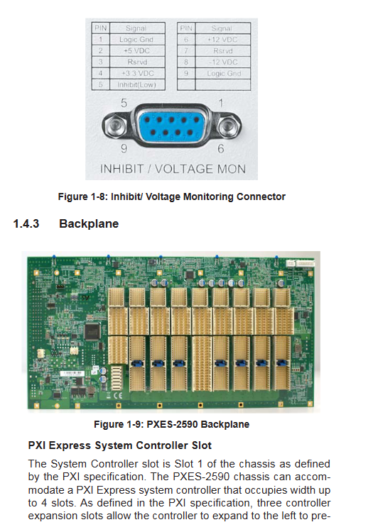
DB9 interface: Inhibit/Voltage Monitor, which can remotely turn off the power and read some power signals;
C13 AC power input port; Grounding post.
Backboard slot description
Slot1 system slot: supports embedded PXIe controllers with a maximum slot width of 4 slots;
Slot5 system timing slot ST: output star shaped trigger signal; When not using star trigger, it can be used as a regular hybrid peripheral slot;
Slot2‑4、 6-9: 7 PXIe hybrid peripheral slots, all compatible with traditional PXI modules;
Bus resources: 8-wire PXI triggered bus; Single end/differential star trigger; Local Bus; 10M/100M global clock.
Packing list, hardware installation
2.1 Packaging List
PXES-2590 chassis, power cord;
Fill baffle kit (1 3-channel baffle, 9 single slot baffles);
CD (driver, FTP Monitor monitoring software, user manual); Paper user manual.
2.2 Hardware installation steps
System controller installation (Slot1): Confirm that the CPU, memory, and storage on the controller have been installed; Release the lock buckle, push it into Slot1 along the guide rail, fasten the lock buckle, and tighten the panel screws; Recommend pairing with Linghua PXIe-3975 embedded controller;
Peripheral module installation (Slot2-9): Select an empty slot, release the lock buckle, slide in the module, fasten the lock buckle, and tighten the screw; Empty slots must be equipped with filling plates;
Rack installation: Keeping the bottom foot pad will block the air inlet, and rack deployment must ensure the bottom air inlet space;
Power on: Connect the AC power cord and press the power button on the front panel to turn on the device.
This chassis is a wide voltage power supply and does not require manual switching of voltage levels.
System monitoring software FTP Monitor
The monitoring function relies on the backplane SMBus and only supports Linghua’s original PXI embedded controller; The third-party controller needs to call the SMBus API to develop its own upper computer.
Three major functional partitions of software
Connect Control
Start/Stop monitoring;
Logging: Custom sampling period, log overwrite/append mode;
Threshold configuration: Save, load, and restore factory alarm thresholds; Check the firmware versions of MCU and FPGA.
Threshold&Control
Target Temperature: Set the chassis temperature corresponding to the fan’s full speed; Default 50 ℃; Logic: 40% duty cycle of fan below 25 ℃, 100% full speed of fan above set temperature; Adjustable range 25-70 ℃;
Fan mode: The software can switch between Auto/Full full speed;
Alarm threshold: DC voltage of each channel (default ± 5%), temperature alarm (default 70 ℃), fan speed alarm (default 800RPM).
Chassis Status
Real time reading of all power rail voltages;
Backboard 5-channel temperature sensor T1-T5 readings;
Three way fan speed; Display the normal/abnormal status of each project.
SMBus Bottom Layer API (Secondary Development Library)
The document fully discloses the SMBus register command, and the chassis monitoring is subordinate to the SMBus slave device address 0xC6h.
Support functions: read various voltages, 5-way backplane temperature, 3-channel fan speed, firmware version; Set fan mode and all alarm thresholds; Reset MCU; Read a large set of state structures of the whole machine in blocks;
All command codes, 16 bit data formats, bit definitions, and read/write timing are fully provided for customers to write custom monitoring programs.
Appendix A: Option PMK-1524 Integrated Display Keyboard Kit
PMK-1524 is an optional accessory that can be installed on the top of the PXES-2590 chassis, transforming the chassis into an integrated portable workstation.
Hardware specifications: 15 inch resistive touch LCD, resolution 1024 × 768; 104 key detachable industrial keyboard+touchpad; VGA+USB interface; Whole machine kit 7.15 kg;
Installation: The back cover and top cover of the chassis need to be removed, and the sliding kit needs to be installed on the top of the chassis; Connect VGA video, USB touch, and keyboard cables;
Software: eGalaxTouch touch driver, supports Windows system; Provide OSD screen menu settings for brightness, contrast, etc.
Appendix B: Troubleshooting and Basic Maintenance
Common Faults
The whole machine cannot be powered on: confirm the AC power cord and socket; Check if the INHIBIT switch on the rear panel is set to DEF;
Power blue LED flashing: One power rail voltage exceeds the limit; After unplugging all modules, try again but still contact the dealer abnormally;
Fan green LED flashing: The fan is obstructed by foreign objects or damaged;
Temperature amber LED flashing: Check the ventilation gap between the bottom air inlet and rear air outlet; Confirm the installation of baffles in all available slots; Contact the manufacturer if there is still an alarm despite normal ventilation;
System startup failure: All peripheral modules are unplugged and the fault locating modules are inserted one by one.
Maintenance points
The chassis weighs 8.8 kg and is handled with chassis handles for transportation;
Power off and unplug the AC power cord before maintenance and cleaning; Wipe the shell and focus on cleaning the dust at the air inlet;
Internal maintenance of the chassis must be carried out by authorized engineers;
Built in backup lithium battery, there is a risk of explosion if the wrong model is replaced.