Lauer LCAstarline (LCA300/LCA320/LCA325) Text Display Screen
Overview, Safety, and Standards
Product positioning: Industrial equipment human-machine interface, displaying fault information, actual process values, and modifying process settings; Support help text, up to 1024 message texts, 256 standby pages, and 256 operation pages.
Compliance certification: CE, compliant with EMC Directive 89/336/EWG; EN50081‑2、EN55082‑2。
Target personnel: Professionals familiar with automation and PC technology.
Safety points
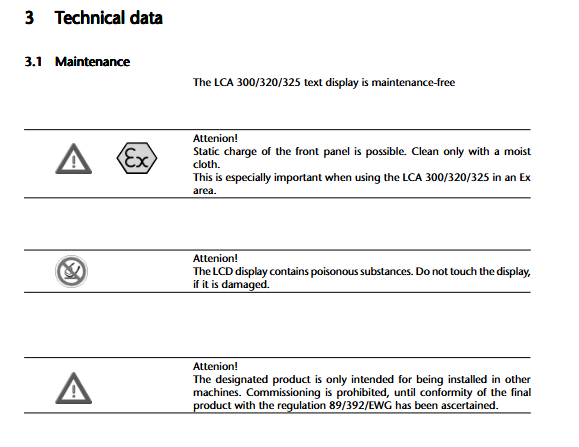
Only installation embedded within the entire machine is allowed, and the machine must comply with mechanical instructions 89/392/EWG before it can be put into operation.
The power supply is a safe ultra-low voltage SELV; The protective ground PE is internally isolated from the power supply 0V, and the casing must be grounded with the PE wire as short as possible.
The front film is prone to accumulating static electricity and can only be wiped with a damp cloth; LCD damage prohibits contact with harmful substances inside.
Factory pre configured for explosion-proof Zone1/2; Explosion proof certification cannot be added after leaving the factory and must be specified when ordering.
Quality support: 48 hour high and low temperature aging test for the entire machine; Provide hotlines and on-site/in-house training.
Hardware specifications and interfaces
2.1 Power Supply
Power supply:+24 VDC ± 20%; Allow a short-term voltage drop of 20ms; Typical power consumption 300mA; 1A slow melting glass fuse with spare fuse.
Power supply terminal 2-pin, maximum wire cross-sectional area of 2mm ².
2.2 Serial interface
25 pin SUB-D (RS232/TTY): PLC communication/PC download project, can also be connected to TTY current loop.
15 pin SUB-D (RS422/485): Bus communication.
9-pin SUB-D (LCA325 only): Printer interface RS232, compatible with LCA710/LCA750 industrial printers.
Different PLCs require dedicated driver programs (corresponding manuals), using the matching adapter cable LCA-7xx.
2.3 Operation panel components
Display: LCD backlight; LCA320/325: 2 lines x 40 characters; BIOS ≥ 201.4 supports multi country character sets; Supports 8 user-defined special characters.
Indicator light
ERR: Always on: firmware/engineering exception, communication not established; Flashing: Communication with PLC interrupted.
PLC, LCA: Mode switching indicator light, PLC-LCA shift button to switch modes.
7 function buttons, each with its own LED; LED supports four states: OFF off, ON constantly on, FLASH flashing (75% on), and INVERSE FLASH reverse flashing (75% off).
Key mode
←/→: Left or right cursor, switch pages;
↑/↓: Translate help/message text, add or remove variables;
EDIT: Enter the operation page overview/exit editing;
HELP: Retrieve the help text bound to the current page;
ENTER: Confirm editing and write the modified values to the PLC.
✅ PLC mode (PLC light on): The key code is directly uploaded to the PLC, and the corresponding bit is set to 1 when the key is pressed, which is used for PLC program processing of key logic.
✅ LCA local mode (LCA light on): internal processing of the panel; Used for flipping pages, browsing messages, and editing variables, the key codes are not uploaded to the PLC.
7 composite button functions (LCA mode):
Backboard: Contrast adjustment potentiometer; ROG jumper (power on display firmware version, used for technical support).
2.4 Physical Machinery
Appearance: 216 × 84 mm; panel hole installation;
Protection: front panel IP65, back panel IP20;
Storage medium: Internal 64 KB Flash EEPROM, storing firmware, engineering text, and variable definitions.
Installation and EMC anti-interference key points
Maintain a distance of ≥ 250mm between the cabinet and interference sources (contactors, frequency converters); Laying of power cables and signal cables in separate cable trays.
The contactor/relay coil must be equipped with a freewheeling diode or RC absorption circuit.
Shielded cables must be used for signal lines larger than 5mm, with both ends of the shielding layer grounded; An equipotential bonding conductor of ≥ 10mm ² is required.
It is recommended to add an external power filter to the power supply.
The protective grounding wire of the shell is short and thick; The power supply 0V is grounded at a single point on the power side, following VDE specifications.
Startup debugging steps
The whole machine is powered off; Connect the 24V power supply;
PC uses LCA733 programming cable to download engineering records (including text, variables, firmware, PLC drivers) through LCAPRO software;
Connect PLC and LCA; Power on;
Warning: LCAPRO software must be used; Incorrect firmware/driver can cause PLC and panel failures.
PLC-LCA communication principle
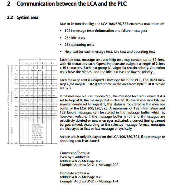
Communication uses 256 byte shared data areas B0… B255. B0-B9 system reserved; B10-B255 Users can freely allocate (message bits, variables). Communication cycle process:
PLC write operation page number;
LCA detects key actions and writes key codes into corresponding bytes;
If editing and modifying the set variable, LCA will write the new value into the corresponding data area;
LCA reads all shared bytes of PLC; Cycle and repetition.
4.1 System Byte Allocation (B0-B9)
B0: Operation page number output;
B1: bit0=Alive heartbeat signal (LCA periodically set to 1, PLC used to determine panel online); Bit1 to bit7: button status;
B2 (LCA325 only): Printer status bit;
B3: Key code; Bit6 shift key status; Bit7 local LCA mode marker;
B4/B5: 7-way button LED control, two bit combination to achieve 4 LED states;
B6: Data recording/language switching bit, supporting two sets of engineering records to achieve multilingual switching;
B7: Priority blocking, message display mode, keyboard lock;
B8: Printing trigger;
B9: Standby text number.
4.2 Priority System (the higher the number, the higher the priority)
Priority 0: Idle: Display standby text when there are no messages or operation pages;
Priority 1 Information message;
Priority 2 Failure message;
Priority 3 Operating operation page;
Priority 4 editing (highest).
The panel automatically displays the current highest activation priority; PLC can mask some priorities through B7 bytes.
4.3 Message System
Up to 1024 message bits (B10.0~B137.7); PLC corresponds to bit 1, and the panel displays the corresponding message text.
Maximum message cache of 128 messages+128 faults; Power outage cache lost.
Message display mode: first message, last message, scrolling display in a loop.
Each message can be bound with independent help text (up to 32 lines), which can be viewed by pressing the HELP button.
4.4 Variable Types (Actual/Preset)
Variables can be placed in standby text, message text, or operation pages. Actual only displays; Preset can be edited on the panel and written back to the PLC after confirmation.
Variable Type Function Description
BIT bit variable PLC one bit, 0/1 displays two custom text segments respectively
STRING string 1 byte, each value from 0 to 255 corresponds to custom text, confirm ENTER before writing back to PLC
CSTRING (manual example equivalent STRING) modification immediately written back to PLC
BINARY (BIN) is an unsigned number; Support decimal point, upper and lower limits, leading zeros; Supports 1 byte/double byte
VBIN signed binary numerical value, positive and negative signs; 1/2 byte
BCD BCD encodes numbers and displays them in decimal format
ASCII characters, display strings
The maximum number of operation pages is 256, with a maximum of 2 lines x 40 characters per operation page, and variables are placed to modify parameters.
Printer function (exclusive to LCA325)
RS232 printing port; LCAPRO software configuration: baud rate 1200-9600, data bits, stop bits, checksum; Handshake mode NONE/XON/XOFF/RTS-CTS; Print output direction.
Two printing triggering methods:
Hardcopy: PLC triggers the rising edge of B8.0, printing the entire content currently displayed on the screen; Print completed B2.0 and set to 1.
Message print: Set B8.1 to 1 and print all messages in the message queue.
Printer status feedback to PLC B2 byte; Communication interruption will abort the printing task.
Editor operation process (modify Preset setting variables)
Switch from PLC-LCA to LCA local mode (LCA light on);
Press EDIT to enter the operation page and select;
Select the corresponding operation page with the cursor keys and enter the page with ENTER;
Position the cursor on the editable Preset variable; ↑↓ Modify numerical values;
Enter to confirm, write the new value into the PLC; The cursor jumps to the next variable;
EDIT exits editing mode.
LCAPRO can be configured with a timeout period and prioritize automatic exit operations without pressing a button.
Maintenance and explosion-proof use
Regular maintenance free; The front panel can only be wiped with a damp cloth;
LCD damage, do not touch the interior;
Explosion proof application: Specify Ex zone 1/2 version when ordering; The whole machine must meet VDE0165; Cannot increase explosion-proof qualifications through later modifications;
The insertion and removal of cables and fuses in the Ex area must be completely powered off.
Supporting software LCAPRO
Running platform MS-DOS/DR-DOS, at least one serial port on PC, 3MB hard disk space;
Function: Select PLC driver; Edit standby/message/operation pages, variable definitions; Download/upload panel project; Generate project documents; Multilingual; Context assistance.
Important: Firmware version ≥ 201.4 is required to support international character sets.