KUKA LBR iico Collaborative Robot Assembly Manual
Product Description
LBR iico is a 6-axis lightweight collaborative robot (Class II ISO10218-1), with all motors and power cables built into the robot arm shell; Each axis integrates triple monitoring of position sensors, torque sensors, and temperature sensors. Robot body composition: base, rotating column A1, link arm A2-A3, forearm A4, inline wrist A5-A6, Commander end unit, built-in electrical wiring.
Commander wrist unit function
LED status indicator light; Hand guided drag and drop buttons; P-point record button; A/B user-defined buttons;
X1: M8 external IO interface; X2:M8, Used for MEMD zero calibration adapter.
Permitted use and prohibited misuse
Permission: The handling tools and fixtures, workpiece processing, and workpiece transportation must meet the specified environmental conditions and follow the maintenance cycle.Prohibited (misuse will result in loss of warranty): use as a climbing ladder, operate beyond parameters, lack safety protection, carry people and animals, outdoors, explosion-proof hazardous areas, radioactive environments, underground mining.
Safety
The safety content of the mechanical arm body document needs to be combined with the KR C5 micro-2 controller manual, which includes more electrical safety content.
Legal explanation: Robots are semi-finished products and cannot be produced separately; The integrator must complete the risk assessment of the entire equipment, install all safety protections, and issue an EC compliance declaration before it can be put into use. The accompanying “Assembly Declaration of incorporation” is provided.
personnel qualification
User side: Implement labor safety and provide regular personnel training;
System integrator: responsible for installing wiring, risk assessment, implementing safety protection, issuing CE, and writing machine operation documents;
Operation/debugging/maintenance personnel: must understand the complete set of manuals and possess corresponding professional qualifications.
regional division
Workspace: reachable range of robot movement;
Danger zone=workspace+stopping and braking distance, must be physically protected; If there is no physical fence, the entire system must meet the requirements of ISO 10218 collaborative robots.
The body comes with protective components
Mechanical hard limit (some shafts come with built-in); Optional adjustable mechanical shaft limit;
Options for manually moving the robotic arm without driving energy (release device, brake release device);
The nameplate and warning signs of the main body must not be torn off or altered.
Important safety measures
Even after a power outage, the robotic arm may still fall due to brake failure. Before power outage maintenance, place the robotic arm in a position that will not fall and cause injury, and additional mechanical support is necessary; Personnel are prohibited from staying under the robotic arm.
The motor operating casing is at high temperature, avoid direct contact; Personnel wearing active implantable devices such as pacemakers should maintain a minimum distance of 300 mm from the motor/brake.
Emergency stop and enable devices require regular testing;
After modifying the hardware/program, prioritize low-speed testing in T1 mode for all programs;
Fault handling: Lock and tag the main switch of the controller, record the fault, and conduct a complete safety function test after repair.
Key safety points for homework scenarios
Transportation: It is necessary to use a transportation posture to avoid impact and vibration;
Debugging and commissioning: changing the factory default password; Check the matching between the robotic arm and the controller; Avoid condensation; Verify all security functions;
Manual mode T1/T2: T1 debugging takes priority, T2 is only used for high-speed testing and does not allow teaching programming;
Automatic mode: All protective devices are intact and there are no people in the danger zone;
Maintenance and repair: When working with live parts, the main power supply must be disconnected and the power must be confirmed to be off; After the controller is powered off, the internal high-voltage capacitor remains charged for several minutes; Electrostatic ESD protection;
Scrap storage: comply with local regulations.
Technical data
Overview of Three Robot Cores
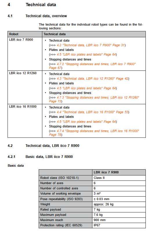
Model LBR iico 7 R900 LBR iico 12 R1260 LBR iico 16 R1000
Rated load 7 kg 12 kg 16 kg
Maximum load 7.6 kg 12.8 kg 17.2 kg
Maximum arm span 900 mm 1260 mm 1000 mm
Body weight 26 kg 40 kg 39 kg
Repetitive positioning accuracy ± 0.03 mm ± 0.04 mm ± 0.04 mm
Protection level IP67, whole machine IP67, whole machine IP67
Installation method: Floor/Ceiling/Wall/Floor/Ceiling/Wall/Floor/Ceiling/Wall/Floor/Ceiling/Wall/Wall/Floor/Ceiling
Controller KR C5 micro-2 KR C5 micro-2 KR C5 micro-2
Environmental conditions: operating temperature 0-45 ℃; Storage -25~60 ℃; Humidity 20-80% without condensation; Some models support cleanroom ISO rating. Gear meshing noise is a normal phenomenon at specific posture and speed, and can be reduced by optimizing motion parameters.
axis parameter
Joint motion range of all models: A1 ± 185 °; A2 -230°~+50°; A3 ±150°; A4 ±180°; A5 ±110°; A6 ±220°; The maximum shaft speed varies among different models.
Tilt installation prompt: When not installed at 0 ° on the ground (wall, ceiling), the robot tilt angle must be filled in the controller software; The motion range of A1 axis will be automatically limited according to the installation angle, and incorrect parameter filling can cause overload and accidental action damage to the equipment.
Load, flange interface, and base stress
Payload diagram: Simultaneously verify the load mass+center of gravity position Lx Ly Lz+moment of inertia; The maximum load is only allowed at the center of gravity 0 position; The KUKA Load tool must be used to calculate the load and write it to the controller. The robot body arm does not allow additional auxiliary loads to be attached.
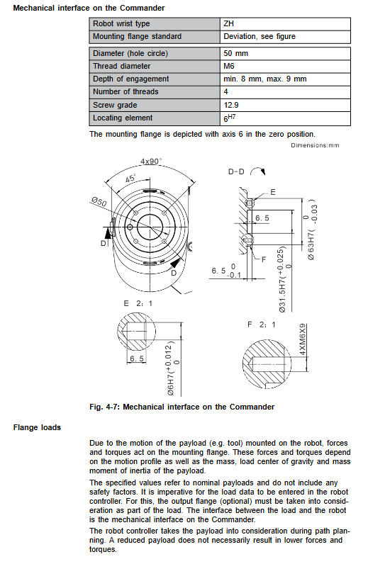
Commander output flange: hole diameter of 50 mm, 4-M6-12.9 grade screws; Positioning pin φ 6H7; The document provides the allowable axial force, radial force, and overturning torque of the flange under operating conditions and emergency stop conditions.
Foundation loads: Provide normal operation, peak vertical force, horizontal force, overturning moment, and A1 torque for three installation conditions: ground, ceiling, and wall; Users must design the base based on this, as insufficient strength of the base can cause it to overturn and collapse, posing a fatal risk.
Stop distance and stop time
Distinguish between STOP 0 (cutting off the drive and closing the brake directly) and STOP 1 controlled shutdown; Test conditions: Single axis motion of A1/A2/A3 main coordinate axis, POV100%, Rated load; Provide stop angle and stop time curves for different elongation rates I (33%/66%/100%) and different mass loads.
STOP0 causes significant damage to robots and should be used as little as possible; Brake wear increases with the number of Stop0 triggers, it is recommended to test the brake at least once a year.
Nameplate labels, REACH regulations
Body nameplate QR code link KUKA Xpert; Do not tear off warning signs; Meet the substance information requirements of Article 33 of the EU REACH.
Planning and Design
Design considerations: The following operating conditions will accelerate component wear and require shortened maintenance cycles or consultation with KUKA technology: long-term temperature limit operation, abrasive dust environment, continuous approach to performance limits, full power start of refrigeration unit, frequent start stop of single axis, long-term static vertical posture, external continuous process force.
Machine frame mounting for rack installation: Use positioning pins and 4 M8-12.9 hexagon socket bolts; Provide installation drawings, and the base structure must meet the stress parameters of the base.
Cables and interfaces
Standard cables: motor cable, data cable, equipotential protection ground wire; Standard length 4 m/7 m/15 m, maximum not exceeding 15 m;
Bending radius: Fixed installation of motor cables ≥ 120 mm; data cables ≥ 60 mm; cables are prohibited from bearing tension; Separate the wiring of motor cables and data cables; Indoor installation;
Base A1 interface: X30 motor connector, X31 data connector;
Wrist Commander interface: X1 (M8 IO: 24V, DI/DO); X2 (M8 for MEMD calibration adapter); The document provides an IO wiring schematic.
Transportation
Before transportation, the robot must enter the designated transportation posture: A1=0 °; A2=-115 °; A3=115 °; A4=0 °; A5=75 °; A6=0 °;
Use qualified lifting equipment; Avoid impact and vibration; Remove transportation protection components; Refer to the drawing for the center of gravity position.
Start up and Resumption
Rack mounted installation steps
Confirm that the robot is in a transport position; Check the strength of the base support;
Install positioning pins and place the robot vertically; Tighten 4 M8 bolts diagonally in multiple stages;
Connect the protective equipotential ground wire (M4 nut, torque 2.8 Nm);
Connect motor cable X30 and data cable X31;
After completion, follow the controller manual to start the system, install tools, and calibrate the zero point.
Tools: torque wrench, complete set of hexagon socket; Once high-strength bolts are loosened, they must be replaced with new bolts.
Detailed description of supporting cables
Motor cables, data cables, and protective grounding wires; Optional X1 external cable, X2 MEMD adapter cable, and external protective grounding wire.
Mobile robotic arm without driving energy
Move the robotic arm in case of emergency power outage; Different models support brake release devices, and the document suggests that operators must receive training on this operation in advance.
Maintenance
Provide a maintenance overview table for three types of robots; Distinguish the inspection items that need to be executed for different running times.
Repair Repair
Fault repair requires contacting KUKA service and using original spare parts.
Decommissioning, Storage, and Disposal
Retired and dismantled: move to transport position, disconnect cables, and remove fixing bolts;
Storage: Clean and protect properly; Follow temperature and humidity storage conditions;
Scrap disposal: Dispose of robots, grease, and electronic components in accordance with local regulations.
Options
Optional accessories: X1 external cable, X2 MEMD zero calibration adapter cable, external protective grounding conductor.