Installation and Operation Instructions for KUKA Robot Arm
Mechanical arm lifting operation with lifting equipment
Tighten 3 lifting rings at the designated position on the base panel;
Connect the rope to the lifting ring and hoisting device, with a tightening torque of 20 Nm;
Use a crane to lift the robotic arm.
Components: ① lifting rings, ② ropes, ③ lifting equipment, equipped with corresponding physical illustrations.
Cable installation
Fix 2 grounding cables at the rear of the base frame;
Refer to the cable identification and connect the cables to the control cabinet and robot interface respectively:
Motor cable XD20.x/XD10. x → X30
Data cable XF21 → X31
Upper arm adjustment
Connect the power supply of the control cabinet and start the entire system;
Use the teaching pendant to adjust the posture of the A1/A2/A3 boom to a horizontal position.
Assemble the robotic arm onto the mounting plate
Clean the lower surface of the hexagonal mounting plate;
Lift the robotic arm to the rack and insert 3 positioning pins into the interface board;
Use 12 M8 × 30-10.9 hexagon socket head screws provided by the customer to fix the robotic arm to the frame, with a tightening torque of 31 Nm.
Parts: ① Cylindrical locating pin, ② Supporting surface, ③ M8 × 30-10.9 hexagon socket screw (provided by the customer) ⚠️
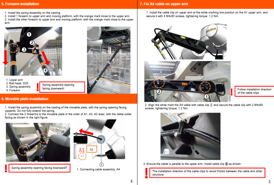
Installation of forearm
Install spring components on the casting, with the spring component opening downwards;
Assemble the first forearm onto the boom and motion platform, with the orange mark near the boom;
Install the remaining forearm with the same requirements.
Parts: ① Big arm, ② D20 ball head, ③ Spring component, ④ Small arm.
Installation of activity board
Install the spring component onto the movable plate casting, with the spring opening facing upwards and the spring not fully stretched open;
Connect the two small arms to the movable board in the order of A1, A2, and A3 axes, and the cable outlet should be oriented according to the diagram.
Fix A4 cable on the boom (A1 boom)
Install cable clamps at the white marked line position on the A1 arm, and tighten them with 4 M4 × 50 screws with a torque of 1.2 Nm;
Align the white mark of A4 cable with cable clamp ①, tighten 2 M4 × 50 screws with a torque of 1.2 Nm;
Ensure that the cable is parallel to the boom and install cable clamp ② as shown in the diagram;
Requirement: Strictly follow the installation orientation of the cable clamp to avoid friction between the cable and other structures.
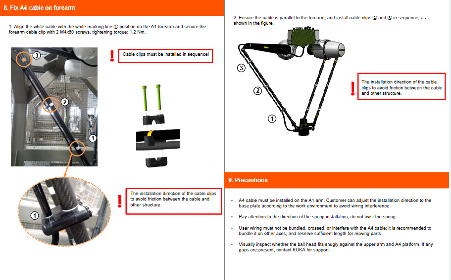
Fix A4 cable on the forearm (A1 forearm)
Align the white mark of the cable with the white mark line ① on the A1 forearm, and fix the forearm cable clamp with 2 M4 × 60 screws with a torque of 1.2 Nm;
Cable clamps must be installed in order; The direction of the cable clamp prevents friction between the cable and other structures.
Ensure that the cable is parallel to the forearm and install cable clamps ② and ③ in sequence.
Installation precautions
A4 cable must be arranged on arm A1; The orientation can be adjusted to the base plate according to the on-site working conditions to avoid wiring interference;
Pay attention to the installation direction of the spring and do not twist the spring;
User wiring must not be bundled or staggered, and must not interfere with A4 cables; Suggest arranging it on other axes, with sufficient cable allowance reserved for the moving parts;
Visually inspect the fit between the ball head and the upper arm, A4 platform. If there is any gap, contact KUKA technical support.
All fasteners are clearly specified with tightening torque, and springs and cable clamps have strict directional requirements. Some components (M8 screws) need to be provided by the customer themselves.