General installation and operation instructions for KUKA KR C4 and KR C4 CK controllers
KUKA KR C4, KR C4 CK universal control cabinet original installation, debugging, maintenance, and repair manual, aimed at engineers with professional backgrounds in electrical, robotics, and Windows systems; The previous KR C4 compact is from the same series, but this manual covers the entire standard KR C4 series and supports CK custom axis schemes.
Product Description
Complete set of robots: robotic arm+KR C4 control cabinet+smartPAD teaching pendant+connecting cables+software+options. Core hardware components of control cabinet:
KPC Control PC: The motherboard has four hardware versions: D2608-K/D3076-K/D3236-K/D3445-K; Responsible for human-machine interface, program, path planning, driver control, communication, and safety monitoring.
KPP KUKA power pack: rectifies AC to generate DC intermediate circuit voltage, supplies power to servo units, integrates brake chopper, and has 5 power versions.
KSP KUKA Servo Package: Each axis servo driver, multiple peak current specifications, performs motor field oriented control.
CCU cabinet control unit=CIB cabinet interface board+PMB power management board; Whole machine power distribution, internal bus communication, safety IO, fan monitoring, battery power failure protection, relying on battery to save location data and controlled shutdown after power failure.
SIB Security Interface Board (Standard/Extended SIB): Implementing discrete dual channel safety input and output, supporting SafeRobot range monitoring options.
RDC rotary transformer digital converter: collects up to 8 axis motor rotary transformer positions and motor temperatures; Divided into regular version and low-temperature RDC-Cool (-30~+55 ℃); EDS non-volatile memory stores origin and configuration data.
CSP controller system panel: status LED, USB, KLI/KSI service network port.
Low voltage power supply unit, backup battery, power filter.
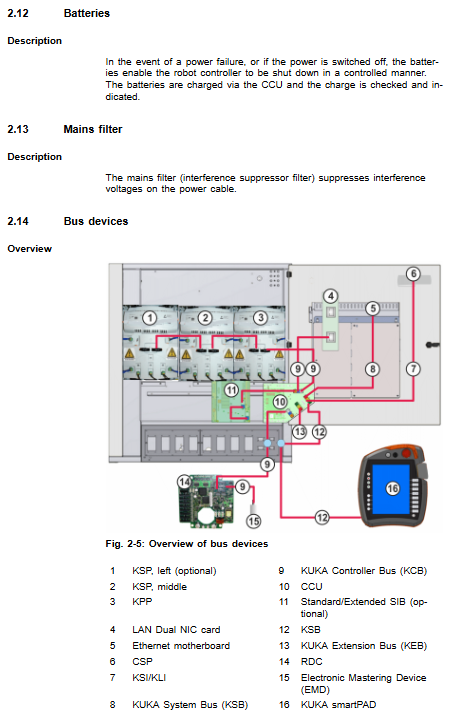
Bus equipment classification KCB/KSB/KEB
KCB: Controller Core Internal Bus (KPP, KSP, RDC, CIB);
KSB: Safety bus (SIB, SION nodes);
KEB: External expansion bus (Profibus, DeviceNet, EtherCAT, digital IO module).
Important constraint of interface panel: Choose between discrete safety interface X11 and Ethernet safety interface X66 (PROFIsafe/CIP Safety), they cannot be enabled simultaneously.
Cooling system: dual circuit cooling; Power device heat exchanger+external fan for heat dissipation; Do not install filter cotton on the ventilation opening as it may overheat and shorten the lifespan of the device.
Permitted use and prohibited misuse ✅ Drive KUKA industrial robots, linear units, positioners, and customer kinematics (CK) compliant with ISO10218-1; ❌ It is prohibited to step on heights, operate beyond parameters, use in explosion-proof environments, and underground mining.
Technical Data
Including the external dimensions of the control cabinet, opening diagram, door swing angle, and minimum maintenance clearance; Environmental temperature, altitude derating, anti vibration and shock parameters; SmartPAD teaching pendant parameters; SIB safety interface electrical parameters; PFH failure rate of safety functions; REACH regulation information; Explanation of nameplate warning labels.
The safety function meets EN ISO 13849-1 Category 3/Performance Level d.
Planning and Design (Pre System Integration)
EMC electromagnetic compatibility: All external cables are shielded cables, and the shielding layer is extensively crimped with PE bars; The control cabinet belongs to Class A industrial equipment.
Installation conditions: requirements for floor installation and stacked installation; The environment prohibits conductive dust and condensation;
PE equipotential grounding mandatory requirement: robotic arm ↔ 16mm ² equipotential cable between control cabinets; The control cabinet body to the PE row of the distribution cabinet is also 16 mm ².
Complete set of motor connectors: Complete list of X20, X7 series, X81/X82 multi axis connector pin assignments, covering standard 6-axis, heavy-duty, palletizing robot, and up to 8 external axis wiring tables.
Discrete security interface X11 (50 core D-Sub Han connector): dual channel test output; External emergency stop, safety door, external enable switch; Comes with a complete wiring schematic and dynamic pulse testing principle; The safety door must be equipped with an external confirmation button and cannot automatically reset and run when closed.
X66 Ethernet safety interface: PROFIsafe/CIP Safety, SafeOperation option; IO byte bit definition;
CIB board EtherCAT interface X44/X65;
System equipment replacement rules: When replacing hard drives, hardware modules, or adding or deleting devices, the system must be reconfigured using WorkVisual software.
Transportation
There are three ways to transport control cabinets: lifting with lifting rings, forklifts, and pallet handling; The optional roller component only allows short distance movement within the cabinet and cannot be transported over long distances; Remove all cables before transportation, close the cabinet door, place them upright, and install anti tipping brackets to prevent tipping and damage to internal boards.
Startup and Re Debugging
Complete power on process:
Check for transportation damage; Ensure minimum maintenance clearance;
Complete PE equipotential grounding;
Laying and connecting motor cables, X21 RDC data cables; Comply with the bending radius of cables;
Install the smartPAD bracket and plug in the smartPAD (X19);
Release the battery discharge protection plug X305; Connect to the main power supply Harting X1;
Power off state plug-in configuration safety interface X11;
Clear personnel and obstacles from the danger zone; Release emergency stop; Close and power on;
Enable Start up startup mode as needed;
Complete machine data verification, TCP calibration, and origin Mastering testing.
Important: When unplugging the teaching pendant, the emergency stop of the pendant will fail, and the system must retain the external emergency stop circuit.
Equipment Operation
Explain the buttons on the smartPAD/smartPAD-2 teaching pendant panel; Hot plug operation process for teaching pendant: Press the disconnect button and wait for 25 seconds before unplugging the plug; Reconnect and wait for about 30 seconds, then perform emergency stop and enable switch function tests again.
The unplugged teaching pendant must be immediately removed from the work area to prevent mixing.
Maintenance
maintenance cycle
Annual: SIB/Extended SIB Relay Output Inspection; Complete functional testing of all emergency stop and enable switches; Clean the fan and radiator according to the degree of dirt;
Fan and battery: replace according to pollution level and battery monitoring status; Maintenance of safety prerequisites: power off and lock, disconnect the incoming power supply; Waiting for the discharge of the intermediate circuit; ESD anti-static throughout the process.
Prohibit direct blowing of compressed air into the interior of the cabinet; Only soft cloth+solvent-free cleaning agent;
Maintenance completed: Check fuses, plugs, grounding, and worn parts.
Maintenance and Replacement
Prioritize maintenance of original spare parts for KUKA; High strength screws of 10.9 and above must be replaced after disassembly and cannot be tightened repeatedly. Complete disassembly and installation steps for each component, including: tool list, spare part material number, safety warning, step-by-step disassembly and assembly, and final functional testing:
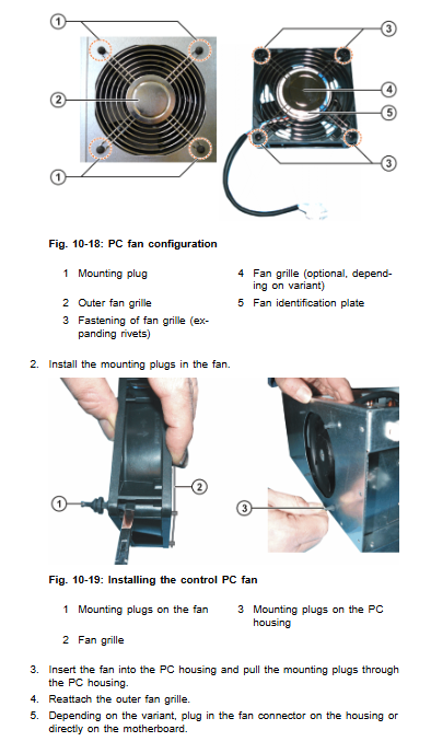
External fan, internal fan module;
KPC controls the entire PC system, PC motherboard button battery, PC fan, HDD/SSD hard drive, and dual network interface card;
KPP power pack, KSP servo pack;
CCU cabinet control unit;
SIB Security Interface Board/Extended SIB Extended Security Board;
RDC rotary to digital converter;
Cabinet battery pack (divided into two battery positions behind the cooling air duct and inside the cabinet door, must be replaced in pairs, paying attention to polarity; batteries stored for a long time should be recharged regularly);
Low voltage power supply unit; Pressure compensation filter plug; Braking resistor; Power filter;
KSS system software installation instructions.
After replacing the hard drive, the system must be reconfigured through WorkVisual or recovery image.
Troubleshooting
Meaning of all LED indicator lights on the CCU board and corresponding troubleshooting plan for faults;
CCU all fuse numbers, rated current, purpose, LED fuse indication;
RDC and CSP system panel LED status;
Four types of motherboard (D2608-K/D3076-K/D3236-K/D3445-K) network port LED status;
SIB security board LED, semiconductor self recovery insurance reset method;
KPP and KSP servo module LED status, alarm/warning message list.
Shutdown, Storage, and Scrap Disposal
Shutdown and return: Remove all external motor cables and grounding wires;
Long term storage: dry, dust-proof, and non condensing indoor environment; Remove the battery sealing interface; Regularly recharge the battery;
Scrap: dispose of according to material classification; Waste batteries are returned to suppliers for recycling as hazardous waste, and the disposal of household waste is prohibited.