KUKA KR CS Box-2 Compact Controller for Four Axis SCARA Robot
KR CS Box-2 is a compact controller for KR SCARA CS series four axis SCARA robots, running KUKA. ControlStudio software and equipped with a smartPAD touch teaching pendant; The protection level of the main body is IP20, and it cannot be used naked in industrial sites; Supports 4-axis SCARA ontology without native external axis capability; Targeting engineering personnel with a background in electrical engineering.
Product Description
Three major internal boards of the whole machine
The Control Board is responsible for HMI human-machine interface, program editing and archiving, motion path planning, servo drive control monitoring, and external device communication.
J6: EtherCAT master station; J5: Interacting with the security board; J501 SD card system burning;
J6001 IO: 24 digital inputs, 16 digital outputs (external 24V provided);
LAN1/LAN2 dual network ports; J1004 TP teaching pendant interface (integrated network port, power supply, emergency stop, three position enable);
The USB interface is paired with physical trigger buttons to achieve one click backup of the entire machine.
Servo Drive servo drive board integrates servo power board and servo control board; Equipped with status LED indicator light.
X1-X5: J1-J4 encoder interface;
S11/S21/S31/S41: J1-J4 motor power output;
X7/X8: Motor brake interface;
X9/X10 EtherCAT input/output; X11 with STO safety IO interface.
Power Protection Board AC incoming line filtering and overcurrent protection; L-IN/N-IN AC input, L-OUT/N-OUT output, PE protective grounding terminal.
External panel interface
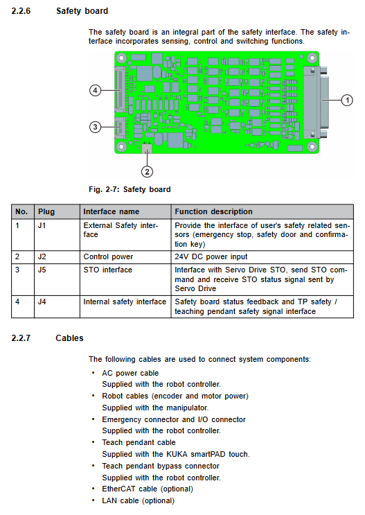
Emergency: external safety interface, dual channel pulse test; Connect external emergency stop, safety door sensor, external enable, confirm button; Equipped with multiple safety status output indicator signals.
Encoder: Feedback plug for mechanical arm encoder;
Motor Power: motor power+brake power plug;
TP: SmartPAD touch teaching pendant dedicated interface;
LAN1, LAN2 Ethernet; EtherCAT; USB; Memory Trigger one click backup button; Power supply AC input socket.
Cooling and installation
Whole machine air-cooled heat dissipation; The designated purpose is to drive only the KR SCARA CS series robotic arm; ❌ Prohibited: Used as a stepping platform, outdoors, explosion-proof, radioactive, underground mining, and operating beyond parameters. Misuse results in the loss of all warranty.
Security Chapter
The controller belongs to partially completed machinery, and the system integrator completes the risk assessment and issues an EC integration statement; Safety level EN ISO 13849-1 Cat.3/PL d.
1) Stop category
Stop0: Immediately cut off the drive and close both the short-circuit brake and motor brake;
Stop1: Controlled deceleration and shutdown of the path, cutting off the drive and closing the brake after shutdown;
Stop2: Keep the drive powered on and perform static monitoring.
2) Personnel Definition
Distinguish between users, system integrators, operators, debugging and maintenance personnel, and cleaning personnel; Only trained and qualified personnel are allowed to install and debug hardware; The system integrator is responsible for risk assessment, implementing security measures, and issuing EC statements.
3) Workplace, hazardous area
Dangerous zone=robot workspace+robot arm stopping distance; To stop the distance test, the robot needs to carry an actual tool load and run it for about 1 hour with a heat engine. Repeat the test multiple times with Stop 1 and take the worst result.
The controller only supports safety door sensors natively; Light curtains and area sensors require users to conduct their own risk assessment and authentication, and the controller hardware is not natively supported.
4) Operation mode
Mode Function Description
T1 manual deceleration mode teaching and debugging requires holding down the enable center position
T2 manual high-speed mode high-speed test, prohibit teaching programming
Auto mode: The machine runs automatically, and the safety door monitoring is effective
Remote mode PLC controls the automatic operation of the whole machine through IO, and the safety door monitoring takes effect
Servo Free: The servo free mode motor is powered off, and the robotic arm can be manually dragged for positioning
T1/T2 mode: Release the enable to trigger Stop2; Press the panic level completely to trigger Stop1.
Servo Free mode: J1/J2 software releases the brake, J3/J4 manually releases it through the mechanical arm body brake release button; Only for rescue positioning, frequent operation may cause damage to the brake.
5) Key safety functions
Emergency stop
SmartPAD touch comes with emergency stop function; Unplug the teaching pendant, the emergency stop will fail; External emergency stop must be configured; Trigger Stop1;
External emergency stop requires a dual channel normally closed contact mushroom head self-locking button.
Three position enabling device: integrated teaching pendant; Support external three position enablement; Multiple people working simultaneously in a hazardous area must be externally enabled; Multi channel enable logic and relationships.
Operator safety – safety door monitoring: only effective for Auto/Remote; Open the door and trigger Stop1; It is prohibited to automatically reset the door when it is closed. An external independent confirmation button ACK-BUTT must be installed outside the safety fence.
Additional protection: software limit switch, mechanical hard limit switch.
6) Mandatory periodic testing
Teaching pendant enable switch, external enable, all emergency stop devices: complete functional testing should be conducted at least once every 12 months.
Test method: During exercise, fully press and hold the panic position for 3 seconds, and the robot must immediately stop without any errors.
7) Key points for homework safety
After a power outage, the maximum voltage in the middle circuit is 450VDC. When unplugging the power cord, it is necessary to wait for 10 minutes for full discharge before opening the cover for maintenance; Strictly prevent ESD and static electricity.
New programs, simulation export programs, and physical machines must be tested in T1 mode.
After a power outage, there is a risk of the robotic arm falling due to its own weight and requires mechanical fixation.
IT Security: Controllers need to be included in enterprise information security management; Change the factory default admin password (factory account admin, password ADMIN).
No teaching pendant operation: The TP interface must be equipped with a bypass connector to simulate emergency stop and enable signals; And remove the idle teaching pendant to prevent accidental operation.
8) Reference standards
Machinery Directive 2006/42/EC, EMC Directive 2014/30/EU, EN ISO10218-1, EN ISO13849-1/2, EN60204-1, etc.
Technical data
Basic Parameters
Power supply: single-phase AC 200-240V, 50-60Hz;
Protection IP20; Overall appearance: 280mm x 310mm x 136mm;
Operating temperature: 0~+40 ℃; Storage -30~+70 ℃; Humidity 20-80% without condensation;
Altitude: ≤ 2000m without power reduction;
Vibration impact: Complies with IEC60068-2-62/27 standard.
Install minimum clearance
The inlet and outlet sides should be ≥ 100 mm; both sides should be ≥ 60 mm; ensure heat dissipation, otherwise it will overheat and shut down.
Installation method: Horizontal placement; Optional bracket for vertical wall mounted installation; Do not block the ventilation openings for heat dissipation.
Nameplate label
High voltage warning and maintenance reminder: Maintenance must unplug the power plug and wait for 10 minutes for discharge; Nameplates and warning labels must not be torn off and must be replaced if they are blurry. REACH SVHC substance information access KUKA Xpert.
System Planning
1) EMC electromagnetic compatibility
Industrial Class A equipment; All external communication cables must be shielded, with the shielding layer extensively grounded.
2) Power supply selection
TN must be grounded to the neutral power grid;
Single robot recommendation: 16A, B-type 30mA leakage protector RCBO;
Multiple robot clusters provide selection references (1-7 ≥ 100mA; 8-25 ≥ 300mA; 26-40 ≥ 500mA).
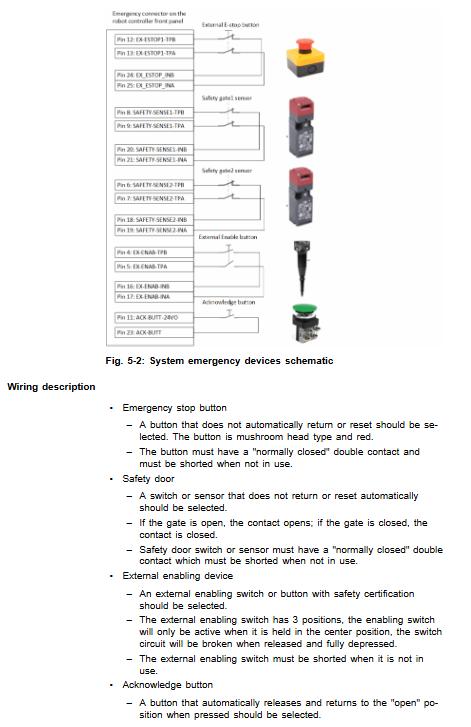
3) Definition and wiring of Emergency safety interface pins
Emergency is a D-Sub connector that outputs TA-A/TA-B dual channel pulses for wire breakage detection;
External emergency stop, dual safety door sensors, and external enablement all use dual channel normally closed passive contacts; Unused channels must be hardware short circuited.
ACK confirmation button: normally open self reset. When installing outside the fence, it needs to be continuously pressed for more than 0.5 seconds to confirm.
The controller outputs three status indicator signals: SAFETY-OUT1-A automatic mode indicator, SAFETY-OUT2-A emergency stop status, and SAFETY-OUT3-A safety door closed indicator, which can be externally connected with indicator lights.
4) IO interface
Digital input: 24 channels, DC24V; The common end can be jumper and supports NPN/PNP sensors;
Digital output: 16 channels; 0-7 channel SSR solid-state relay, configurable with NPN/PNP; 8-15 fixed NPN; The inductive load of the relay must be connected in parallel with a freewheeling diode.
5) Communication interface
LAN1/LAN2: 100M Ethernet, connect to PC to run KUKA. ControlStudio; Cat5 shielded network cable;
EtherCAT RJ45, Servo bus, connected to servo drive.
6) Protecting equipotential PE
Manipulator ↔ 4 mm ² copper wire must be used for equipotential connection between controllers; The controller body is connected to the main PE row in the factory area.
7) Cable laying
Separate wiring for power motor cables and encoder data cables; Cable should be protected against pulling and stress release to avoid tripping risks.
Transportation
Transportation prerequisites: All cables should be unplugged, the cover plate of the casing should be closed, and it should be placed horizontally; Use pallets and forklifts for transportation; Avoid impact and falling.
Power on and restart
Complete startup and operation process
Visual inspection of transportation damage; Confirm that there is no condensation inside;
Controller in place; Horizontal placement or vertical wall mounting with brackets, strictly adhering to heat dissipation gaps;
Connect the mechanical arm controller PE equipotential protection grounding;
Connect the motor power cable and encoder cable, tighten the threads to prevent loosening;
Connect to the Emergency security interface (power-off plugging, hot plugging is prohibited);
TP interface: connected to smartPAD touch teaching pendant; If there is no teaching pendant, a bypass connector must be connected;
LAN/EtherCAT/IO wiring as needed;
AC single-phase power plug connection, locking buckle; The power switch can be equipped with a padlock;
Confirm that there are no people in the danger zone and all safety equipment is in good condition; Close the power switch and turn on the power;
Login to the system, default account admin/ADMIN, password must be changed before operation;
Software debugging: mechanical origin calibration, load setting, IO configuration, automatic mode parameter configuration.
All interfaces are prohibited from being plugged in or unplugged with power on, as it may damage the hardware.
Run
Equipment priority: Emergency stop devices (external emergency stop, teaching pendant emergency stop, safety door) have the highest priority; Secondly, the teaching pendant PC、 Confirm button, external PLC.
No teaching pendant operation: The TP interface must be equipped with a bypass connector; Fault resolution must rely on external ACK confirmation button reset; Remove the removed teaching pendant from the work area.
Maintenance
Mandatory maintenance: Disconnect the AC power plug, wait for 10 minutes for the intermediate circuit to discharge, ESD protection; Do not spray compressed air for cleaning.
maintenance cycle
Every 3 months: Clean the dust filter screen;
Every 12 months: clean ventilation holes; Complete functional testing of the entire set of safety equipment (emergency stop, enable).
Cleaning: Only use dust-free cloth and neutral solvent-free cleaning agent; Do not allow liquids to enter the interior.
Repair
Repairs are only allowed to be carried out by authorized personnel of KUKA; Original spare parts must be used; Users are not allowed to perform board level repairs on their own. Pre condition for maintenance: Power off and unplug the power cord, wait for 10 minutes for discharge, lock and tag, ESD protection.
Troubleshooting
Front panel status indicator lights: 2 red LEDs (Emergency Stop, Error); 2 green mode LEDs; 4-digit 7-segment digital scrolling display fault code.
USB one click backup function: Insert a USB flash drive, press the Memory Trigger button to automatically generate a bckp_timestamp backup package, including zip backup, IP text, and MD5 verification file; Cannot directly migrate and restore the entire machine to another controller, only limited to local backup.
A large number of fault code tables: motion error, tracking error, EtherCAT bus error, drive fault, encoder fault, overvoltage and undervoltage, overheating, brake failure, topology change, IO error; Each entry includes: fault prompt, cause, and countermeasures; Simultaneously containing the underlying DriveMasterMA servo drive fault code (starting with 0x in hexadecimal).
Typical high-frequency fault: EtherCAT topology change requires IO Remapping to rescan the bus topology.
Discontinue, store, and dispose of scrap
Retired shutdown: Power off, unplug all plugs, and remove cables;
Storage: Indoor dry and dust-proof; Dismantle the battery and store it separately; Seal the interface, dust cover+desiccant; Avoid condensation;
Scrap: Circuit boards are used as electronic hazardous waste; Batteries are prohibited from being discarded as household waste and need to be recycled; Classification and disposal of metals and plastics.