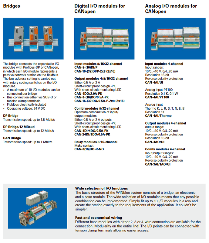
Micro Innovation WINbloc Distributed Remote I/O System
Core functions of Bridge module
The bridge module serves as the interface on the bus master side, connecting the expandable I/O module in the later stage to the fieldbus; Each I/O module appears as a passive slave node on the bus.
Station address setting: Set the bus address for the rotary encoding dip switch of the I/O module body.
Bus physical interface: D-Sub connector or spring crimping terminal; Fieldbus electrical isolation.
Power supply: Operating voltage 24 VDC.
Bridge model specifications
table
Model Bus Type Maximum Baud Rate
DP Bridge Profibus‑DP 1.5 Mbit/s
DP Bridge/12 MBaud Profibus‑DP 12 Mbit/s
CAN Bridge CANopen 1 Mbit/s
A maximum of 10 I/O modules can be connected in series behind a single bridge.
Classification of CANopen series I/O modules
All modules are directly connected to the CAN Bridge; It is divided into digital input, digital output, hybrid module, relay output, and analog module.
1. Digital Input Module (DI)
CAN-8- (16) DI/P: 8-way/16 way digital input
CAN-16- (32) DI/P -2×8: 16/32 digital inputs, internal 2 × 8 grouping
2. Digital output module (DO), PK represents short circuit protection, with short circuit status LED indicator light
CAN-4DO/2.0A-PK: 4-channel output, 2.0A per channel, short circuit protection
CAN-8- (16) DO/0.5A-PK: 8/16 outputs, 0.5A per output, short circuit protection
CAN-16- (32) DO/0.5A-P-2×8: 16/32 outputs, 0.5A, 2 × 16 grouping
3. Digital combination module Combi (DI+DO, PK with short circuit protection)
CAN-4DI/4DO/0.5A-PK: 4 inputs+4 outputs, output 0.5A
CAN-24DI/8DO/0.5A-PK: 24 inputs+8 outputs, output 0.5A
4. Relay output module
CAN-8 (16) DO-R-NO: 8-way/16 way relay normally open contact output
5. Analog input AI
CAN-4AI/UI: 4-channel universal analog signal; Range ± 10 V/0…+10 V/0… 20 mA/4… 20 mA; 16 bit resolution, reverse polarity protection
CAN-4AI/PT100: 4-channel PT100 thermistor; Resolution 0.1 K
CAN-4AI/Thermo: 4-channel thermocouple; Support K, J, R, S, T, N, E, and B type thermocouples; Resolution 1 K
6. Analog output AO
CAN-4AO/UI: 4-channel analog output; ± 10 V/0-10 V/0-20 mA/4-20 mA; 16 bit, reverse polarity protection
7. Analog mixing module
CAN-3AI/1AO/UI: 3-channel analog input+1-channel analog output, universal voltage and current signal.
Base module and wiring characteristics
System three-layer structure: Bridge module+I/O electronic module+Base module.
The base has 2-wire/3-wire/4-wire wiring versions to choose from.
The IO point terminal adopts a tension clamp terminal, which is convenient for wiring.
Modular assembly: Up to 10 I/O modules can be assembled side by side with snap fasteners, combining input and output as needed to achieve customized remote IO stations.
Key points of the overall system
Physical layer: bus electrical isolation; Unified 24VDC power supply;
Address: Each I/O module uses a rotary encoder switch to independently set the bus station number;
Output PK model: Built in short-circuit hardware protection+short-circuit LED status indication;
Simulation modules generally have reverse polarity protection; 16 bit analog quantity, dedicated module for thermistor/thermocouple.