Micro Innovation MICRO PANEL GF1 Color Touch Human Computer Interface
Swiss Micro Innovation AG; GF1 is a color touch human-machine interface designed for medium to high complexity automation systems. Unlike the previous GS-2, which belongs to the same brand and has a different product line: GS-2 is an EL monochrome screen and SMM memory module; GF1 is a TFT color screen, PCMCIA card storage project, and dual expansion communication slots; The engineering software is GALILEO (Run Time GRS).
Product version (mainly for 10.4-inch models GF1-10xxx)
Model Display Screen Resolution Power Supply
GF1-10TVD 10.4 “TFT color LCD VGA 640 × 480 24 VDC, electrically isolated
GF1-10TVB 10.4 “TFT color LCD VGA 640 × 480 24 VDC, non isolated
GF1-10MVA 10.4 “TFT color LCD VGA 640 × 480 100-240 VAC, 50/60Hz
All models can choose the 1.4301 stainless steel corrosion-resistant front panel version.
Mechanical parameters of 10 inch model
Overall appearance: 342 × 270 × 85 mm, weight approximately 4.8 kg
Control cabinet opening: 316 × 244 mm; M5 mounting screw
IP65 front panel: requires separate ordering of rear compression frame kit, not included in the supply; The back protection of the device is IP20.
Standard Supply List
Host, PC card fixing pressure piece, Slot1 blind cover plate, 4 M5 fixing screws, panel sealing gasket, power plug, paper manual.
PCMCIA engineering storage cards are not standard and need to be purchased separately.
Installation requirements
Two installation methods:
Front mounted version: 4 countersunk screws, tighten directly in front of the cabinet, no operation required at the back of the cabinet;
Rear bolt version: Requires space behind the cabinet and nuts and washers for locking.
Heat dissipation: minimum ventilation gap of 10cm around; The heat dissipation gap must not be obstructed; Vertical installation; The highest altitude is 2000 meters.
Working environment temperature: 0~50 ℃ inside the cabinet; Storage -20~60 ℃, no condensation.
Do not expose the screen to direct sunlight, as UV rays and high temperatures can damage the LCD.
After installation, it is necessary to ensure that the storage card, buttons, backplane interface, and LED indicator lights are accessible; The cable must meet the bending radius requirement.
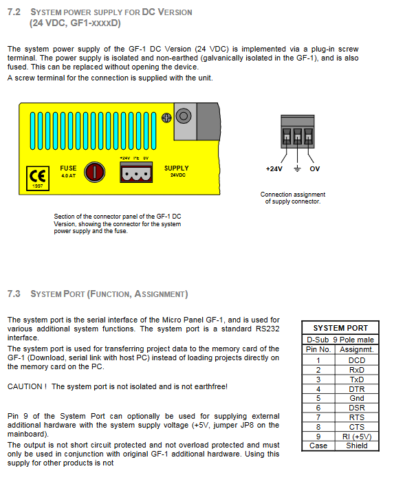
Backplane interface and power supply
1) AC Communication Version GF1-xxxxA (100-240VAC)
Three core pin power socket: L live wire/N neutral wire/PE protective ground; Built in replaceable 4.0AT insurance, can be replaced without disassembling the device.
The PE protection ground must be reliably connected to prevent electric shock.
The maximum power consumption is 40W.
2) DC version GF1-xxxxB/GF1-xxxxD (24VDC)
3-pole Phoenix plug-in terminal:+24V, PE, 0V; Built in replaceable 4.0AT insurance.
Effective voltage range 20.4~28.8 VDC; Ripple limit 18.5-30.5 VDC; Typical current 1A; maximum impulse current 3A, lasting for 2 seconds.
3) System Port (9-pin D-Sub male, non isolated RS232)
Purpose: Download engineering programs on PC; Serial port debugging. Pin: 2-RxD, 3-TxD, 5-GND; 9-pin RI can be jumper JP8 output+5V, limited to original accessories, prohibited from external third-party peripherals, no short circuit protection; The shell is shielded.
Storage: PCMCIA (PC Card) memory card slot (Slot0)
All project images are saved on PCMCIA I/II flash cards (up to 64MB, supporting ATA Flash).
Two ways to download projects: 1) PC computer with PCMCIA slot, directly write the project to the memory card, and then insert it into HMI; 2) The PC downloads the project to the card online through the System Port (RS232) serial port.
The card provided with the device must be used to secure the pressure piece; When installed vertically, vibration without pressure components can cause the storage card to detach.
The operating system is GRS (Galileo Runtime System).
Expansion Slot Slot0/Slot1
Slot0: Fixed as a PCMCIA memory card slot.
Slot1: Communication expansion slot; Both slots (Slot0+Slot1) can accommodate communication cards and can run two different fieldbuses simultaneously.
Attention: When plugging or unplugging communication boards, power must be turned off and ESD static protection must be taken into account. Only Micro Innovation original boards are allowed.
Infrared Touch Screen
Working principle
Infrared matrix touch, 70 infrared channels; X/Y-axis infrared beams are obstructed by fingers to recognize touch;
Large area pressing greater than 20mm x 20mm will not be recognized; Channels that are continuously obstructed will be blocked by the controller and will no longer participate in detection.
Power-On Self-Test
Automatic self check of all infrared channels every time the device is turned on; If some channel signals are below the threshold, the screen will report a fault and the DEF/DIRTY indicator light will turn on; Most of them are caused by dust accumulation on the front frame, but the touch screen is still usable; Severe dirt can cause partial touch area failure.
Maintain cleanliness
Wipe the plastic frame of the front panel with a soft damp cloth; The panel material is PMMA organic glass. The use of solvents and highly corrosive cleaning agents is strictly prohibited as they may corrode the plastic frame; Do not touch the screen during the power on self-test phase as it may interfere with the self-test calibration.
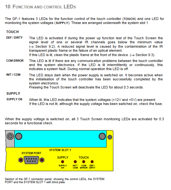
Backboard status LED indicator light (below Slot1)
Supply OK: The system’s+5V and+12V power supplies are normal. All LEDs briefly self check and light up for 0.3 seconds when powered on.
TOUCH group
Initialization/COM: Touch controller initialization completed; When touching the screen, it briefly turns off for about 0.3 seconds.
COM ERROR: Communication failure between touchpad and motherboard, constant light indicates hardware failure.
DEF/DIRTY: Infrared channel signal attenuation, indicating that the front panel plastic frame is dirty and needs to be cleaned.
EMC Cable and Shielding Treatment Specification
All data communication cables must be copper braided shielded cables, using metal shell D-Sub connectors; The power cable does not need to be shielded.
Shielding layer processing technology (completely consistent with GS-2 manual): Strip the wire, shorten the shielding braided layer by about 3cm, and fold it outward to wrap the sheath; Heat shrink tubing wrapping, with a reserved 5-8mm exposed shield; Crimp the clamp on the metal shell of the joint to achieve low impedance grounding.
HMI and PLC are placed in different control cabinets: equipotential connection wires must be added to prevent large compensation currents from flowing through the shielding layer and burning out the shielding contacts.
Even if the other end is not wired, shielded wires must be used for communication cables as long as they are connected to the HMI side.
EU Compliance
Meets EU EMC Directive 89/336/EEC and low voltage 73/23/EEC;
Electromagnetic emission: EN50081-2; Anti disturbance EN50082-2; Safety standard EN60950.