Yaskawa F7 series (CIMR-F7U) frequency converter
Basic Information and Scope of Application
Applicable models: CIMR-F7U (208-240V/480V full series)
Power coverage: 0.5~500HP (0.4~315kW)
Software version: V3020
Protection level: IP20/NEMA Type 1
Two operating modes:
Overload HD (C6-01=0): 150% overload for 1 minute, carrier frequency 2kHz, maximum 300Hz
Standard ND (C6-01=2): 110~120% overload for 1 minute, maximum carrier frequency 15kHz, maximum 400Hz
Safety regulations (mandatory)
Personnel qualification: Only for professional electrical personnel to operate
Power off operation: Wait for 5 minutes after power off+confirm that the CHARGE light is off+measure bus voltage<50V
Prohibited items:
It is strictly prohibited to connect capacitors or LC/RC filters to the output end
It is strictly prohibited to conduct voltage withstand tests on frequency converters
It is strictly prohibited to plug and unplug operators and terminals with power on
Grounding requirements:
208-240V model: Grounding resistance * *<100 Ω**
480V model: Grounding resistance * *<10 Ω**
Physical installation
Installation requirements
Environmental temperature: -10~+40 ℃ (closed type)/-10~+45 ℃ (open type)
Humidity: ≤ 95% RH, no condensation
Installation direction: Must be installed vertically
Heat dissipation gap:
Up and down: ≥ 50mm (small models)/≥ 120mm (large models)
Left and right: ≥ 30mm
Dimensions and Weight
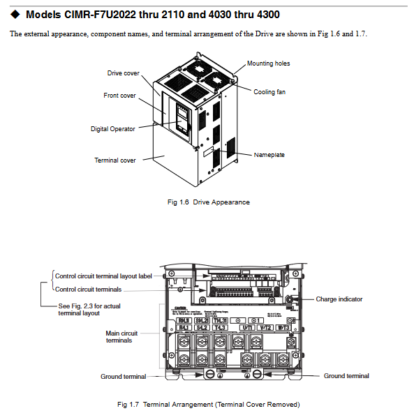
Low power (≤ 18.5kW): NEMA 1 enclosure, weight 3-24kg
High power (≥ 22kW): open chassis, weight 57~404kg
Electrical wiring (core)
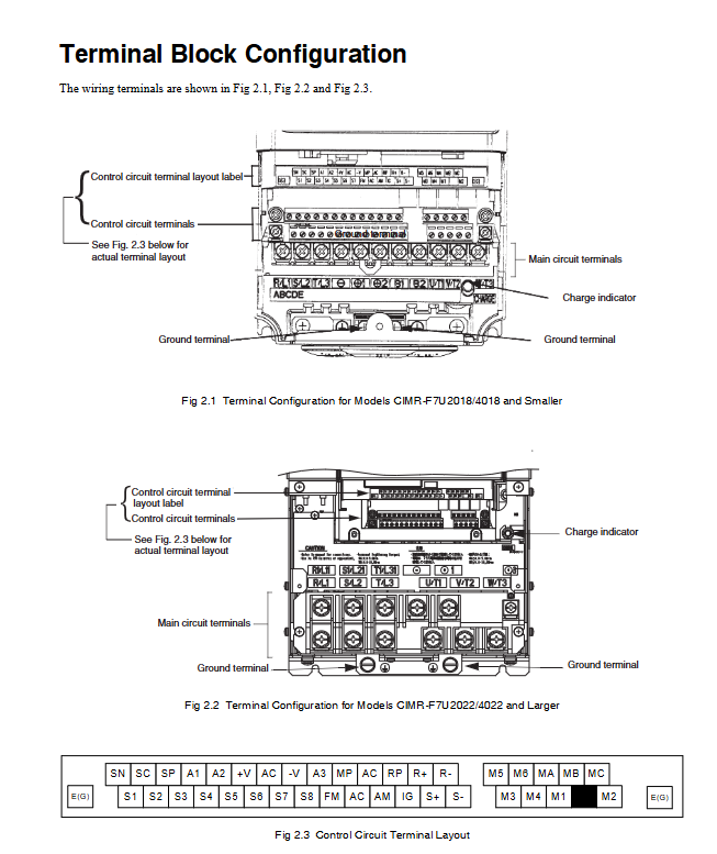
1. Main circuit terminal
Terminal function
R/L1, S/L2, T/L3 three-phase power input
U/T1, V/T2, W/T3 frequency converter output → motor
B1 and B2 brake resistor connection
+, – DC bus
E (G) grounding terminal
2. Control circuit terminals
Digital input: S1~S8 (forward rotation, reverse rotation, fault reset, multi-stage speed, etc.)
Analog inputs: A1 (0~10V), A2 (4~20mA), A3 (auxiliary given)
Digital output: M1~M6 (running, zero speed, frequency reaching)
Relay output: MA/MB/MC (fault alarm)
Communication: R+, R -, S+, S – (RS-485 Modbus)
3. Wiring specifications
Motor line length: ≤ 50m (carrier frequency ≤ 15kHz); ≤100m(≤10kHz); >100m(≤5kHz)
Wire diameter: matched according to current, voltage drop ≤ 2%
Shielding: The power and control lines are laid in separate slots, and the shielding is grounded at one end
Digital manipulator
5 major menus
-DRIVE -: Operation monitoring (frequency, current, voltage)
-QUICK – Quick settings (control mode, acceleration/deceleration, motor parameters)
-ADV -: Full Parameter Programming
-VERIFY -: View modified parameters
-A. TUNE -: Automatic tuning
Common buttons
Local/Remote Switching
RUN/STOP: Run/Stop
JOG: Jogging
DATA/ENTER: Confirm
RESET: Fault reset
Startup and Debugging
Debugging process
Confirm wiring and grounding
Power on inspection
Quick settings: control mode, input voltage, acceleration/deceleration time
Input motor nameplate parameters: power, voltage, current, frequency, number of poles
auto-tuning
Test run, check steering, adjust parameters
Automatic tuning mode
Standard tuning: Motor unloading, rotation measurement (recommended for vector control)
Non rotating tuning: The motor is loaded and does not rotate
Resistance tuning only: used for V/F control
7、 Basic Programming (Key Parameters)
Core parameter table
Typical parameter function settings
A1-02 control mode 0=V/F, 1=V/F+PG, 2=no sensing vector, 3=magnetic flux vector
B1-01 frequency command source 0=panel, 1=terminal, 2=communication
B1-02 Running Command Source 0=Panel, 1=Terminal, 2=Communication
C1 01/02 Acceleration and deceleration time 0.0~6000s
C6-02 carrier frequency 2-15kHz (long line down carrier)
E1-01 input voltage 240V/480V
E2-01 motor rated current according to motor nameplate
L1-01 motor overload protection 1=standard motor, 2=strong cooling motor, 3=vector motor
Fault diagnosis and handling
Common Faults
Handling of fault code meanings
OC overcurrent check for short circuit, load, and acceleration time
OV DC overvoltage prolongs deceleration time and adds braking resistance
GF grounding fault check motor insulation and wiring grounding
LF output phase loss check wiring, terminals, and motor windings
OH heat sink overheating cleaning fan, improving ventilation
OL1 motor overload check load, adjust protection curve
OL2 frequency converter overload increases frequency converter and reduces load
Reset method
Press RESET on the operator
Power off and restart
External terminal reset