KEB COMBIVERT F4 series frequency converter
1. Basic information
The KEB COMBIVERT F4 series frequency converter (C/S version control board) 2004 version English operation manual covers safety specifications, terminal wiring, panel operation, CP parameter setting, fault diagnosis, and password management. It specifies key requirements such as 5-minute power-off maintenance, digital support for 13-30VDC, analog adjustable 0-10V/0-20mA/4-20mA, and is suitable for industrial motor speed regulation and protection scenarios.
2. Safety operation requirements
Only professional electrical personnel are allowed to install, wire, and debug
After power failure, the capacitor in the middle circuit is still charged and must wait for 5 minutes before operation
Compliance with standards: DIN VDE 0100, IEC1000, EN 60204-1, EN 55014, EN 50082-2
Relays connected to inductive loads require the installation of freewheeling diodes for protection
3. Control terminal wiring (core)
C-version terminal X1 (23 pin)
Terminal group functional specifications
X1.1-3 Fault Relay Default Fault Indication
X1.4-5 multi-stage speed I1/I2 3-stage fixed frequency
X1.10-11 Forward Rotation F/Reverse Rotation R Forward Rotation Priority
X1.17 Simulate Given REF 0-10V/0-20mA/4-20mA (CP24)
X1.19 Enable ST to run with power on
X1.20 Reset RST Fault Clearing
S-version terminal X1 (14 pin)
Simplify interfaces, merge enablement+reset ST/RST
Analog quantities, relays, and multi-stage logic are consistent with version C
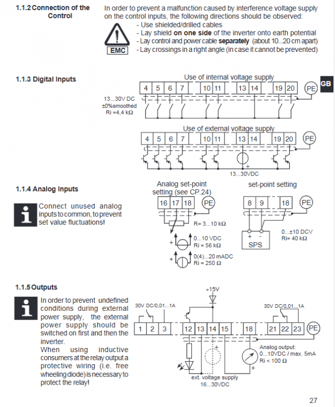
EMC Wiring Specification
Use shielded cables, with the shielding layer grounded on one side
The distance between the control cable and the power cable is 10-20cm, intersecting at a 90 ° angle
Digital power supply: 13-30VDC, analog input impedance 4k Ω/40k Ω
4. Operation panel and display
Panel: 5-digit LED, FUNC/UP/DOWN/START/STOP/ENTER/F/R keys
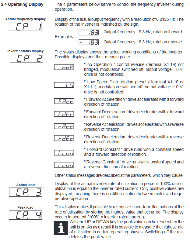
Display item:
CP1: Actual frequency (resolution 0.1Hz)
CP2: Running status (noP/L5/FAcc/FCon, etc.)
CP3: Actual load (* * 1% * * accuracy)
CP4: Peak load
Parameter modification: FUNC switch number/value, UP/DOWN adjustment, ENTER save
5. Core CP parameter table
Parameter function adjustment range default value accuracy
CP.5 Rated frequency 0-409.58Hz 50.0Hz 0.0125Hz
CP.6 Torque increase 0-25.5% 2% 0.1%
CP.7 Acceleration time 0.01-300s 10s 0.01s
CP.8 Deceleration time 0.01-300s 10s 0.01s
CP.9 Minimum frequency 0-409.58Hz 0Hz 0.0125Hz
CP.10 Maximum frequency 0-409.58Hz 70Hz 0.0125Hz
CP.14 Accelerated current limiting 10-200% 140% 1%
CP.15 Constant speed current limit 10-200% 200% 1%
CP.20 DC braking mode 0-9 7 1
CP.21 Braking time 0-100s 10s 0.01s
CP.24 Analog range 0-2 (0-10V) 1
6. Drive mode
Activation: Enter CP0 password
Operation: Panel controls start stop, direction change, and frequency setting separately
Exit: Press and hold FUNC+ENTER for 3 seconds in shutdown mode
7. Fault diagnosis
Common faults:
E. LP: Undervoltage (low input/incorrect wiring)
E. OP: Overvoltage (input high/deceleration too fast)
E: Overcurrent/grounding fault
Overheating: Internal temperature>70 ℃, poor heat dissipation
Reset: After clearing the fault, press RST terminal or ENTER+power off and restart
8. Password Management (CP.0)
Mode 1: Parameter Read Only
Mode 2: Parameter Read and Write
Mode 3: Activate Drive Mode
Factory password free, 0-9999 password can be set to prevent accidental operation
Key questions and answers
Question 1: Why do we have to wait for 5 minutes to operate the KEB F4 frequency converter after it is powered off?
Answer: After the inverter is powered off, the middle circuit capacitor still carries high voltage. Waiting for 5 minutes can ensure that the capacitor is completely discharged, avoiding the risk of electric shock, which is a mandatory safety requirement.
Question 2: What is the core difference between the C and S version control terminals?
Answer: Version C has a 23 pin X1 terminal, with complete functionality including independent enable ST, reset RST, and differential reference; The S version features 14 pin simplified terminals, merging ST/RST and eliminating some expansion interfaces, resulting in simplified wiring.
Question 3: What is the function of the CP.24 parameter and what are the three signal configurations?
Answer: CP.24 is used to set the input range for * * C version simulation given REF (X1.17) * *, with three configurations:
0:0-10VDC (default)
1:0–20mA
2:4–20mA