OMRON 3F88L-160/162 cam locator
Product positioning and model
This document is the specification sheet for Omron 3F88L-160/162 cam locator, which is used for precise timing control of industrial equipment rotation angle to improve accuracy and production efficiency.
3F88L-160: 16 cam outputs
3F88L-162: 32 cam outputs
System configuration
The device consists of the following parts:
Cam locator host
Rotary Transformer: 3F88L-RS15/RS15W/RS17/RS17T
Specialized connection lines: resolver line, cam output line
Display Unit: M7E (M7F discontinued)
Upper controller: Omron SYSMAC CS/CJ series PLC
General specifications (key parameters)
Project parameter values
Power supply voltage 100-240VAC, 50/60Hz
Allowable voltage 85-264VAC
Power consumption of 27VA Max
Impulse current 40A/10ms Max
I/O power supply 24VDC/145mA
Insulation resistance ≥ 20M Ω (500VDC)
Withstand voltage 2300VAC/1min
Working temperature 0-55 ℃
Storage temperature -20-75 ℃
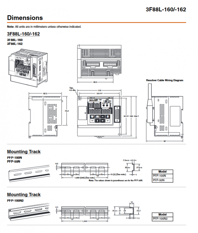
Size 110 × 100 × 82.5mm (W × H × D)
Weight ≤ 1kg
Installation method: Screw installation/DIN rail installation
Performance characteristics
Project 360 resolution 720 resolution
Allowable speed 1600r/min and 800r/min
Control unit 1 ° 0.5 °
Program steps 180 steps/path 360 steps/path
Storage groups (Banks) 8 groups 4 groups
Repetitive accuracy ± 0.2 °± 0.2 °
Detection cycle ≤ 100 μ s ≤ 100 μ s
Output type open collector electrode, 26.4VDC/300mA
Three working modes
RUN mode: normal operation, online angle adjustment, origin offset
PRGM mode: Cam program editing, deletion, test run
SET mode: parameter setting, compensation setting, teaching demonstration, communication configuration
Third level functional permissions
Level 0: Only monitoring, prohibiting modification of programs and parameters
Level 1: Basic operations, capable of writing cam programs
Level 2: All functions are open, including advanced application features
Core functions
Basic functions
Cam programming: Set output ON/OFF according to rotation angle, supports panel/computer writing
Group switching: Use BANK1-3 signal to switch the running program group
Data storage: EEPROM non-volatile storage, no battery required
Monitoring: Real time display of current group, speed, and angle
Advanced application features
Origin compensation: Set any angle to 0 °
Gap compensation: eliminating mechanical return errors
Advance angle compensation: automatically triggers the angle in advance with the speed
Teaching function: manually rotate and directly input angle parameters
Copy function: Batch copy parameters and programs
Output hold: Maintain output state during abnormal/switching mode
Communication: Supports CompoWay/F protocol, read/write and monitoring
Input/output
Control inputs: START, TRIG, BANK1-3, RESET (optocoupler isolation)
Control outputs: RUN, ERROR, M · DET
Cam output: -160 is 16 points, -162 is 32 points
Certification and Usage Standards
Certified by UL/CSA, compliant with EC directives
Prohibited for use in high-risk situations such as life safety
Specifications may be updated, subject to official approval
Key issues
What is the core difference between F88L-160 and -162?
Answer: The only difference between the two is the number of cam output channels: 3F88L-160 has 16 channels of output, while 3F88L-162 has 32 channels of output, with completely identical power supply, performance, and functionality.
Question 2: What are the key impacts of 360 and 720 resolutions on device usage?
Answer: Resolution determines control accuracy and upper limit:
360 resolution: 1 ° accuracy, supports 8 sets of programs, up to 1600r/min
720 resolution: 0.5 ° accuracy, supports 4 sets of programs, up to 800r/min
Question 3: How is the data of the cam locator saved and does it need maintenance?
Answer: The parameters and cam program are stored in EEPROM non-volatile memory, which can be erased and written 100000 times without the need for battery backup or daily maintenance.