I/O module for Siemens 3RK series AS-i SlimLine Compact control cabinet
Basic Overview
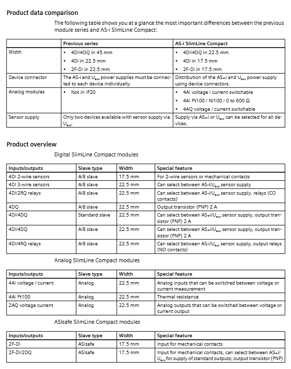
Applicable products: Siemens 3RK series AS-i SlimLine Compact module
Installation environment: inside the control cabinet, IP20 protection level
Core advantages: ultra narrow width (17.5mm/22.5mm), easy wiring, high compatibility, strong diagnosis
Module classification and specification
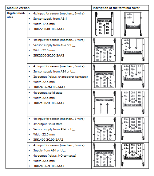
Type Typical Model Width Core Features
Digital quantity modules 3RK2200, 3RK2400 17.5/22.5mm 4DI/4DQ, PNP output 2A/channel, relay output
ASIsafe safety module 3RK1205, 3RK1405 17.5mm 2-channel safety input SIL 3 / PL e / Cat.4
Analog modules 3RK1207, 3RK1107 22.5mm 4AI/2AQ, current/voltage/thermistor switching, 15 bit resolution
Core functional characteristics
wiring method
Screw terminal: torque 0.6~0.8Nm
Push in: quick connect without screwdriver, wire diameter 0.5~1.5mm ²
Power supply selection
Sensor power supply: AS-i bus or Uaux 24V DC dip switch
Uaux power supply: maximum 500mA, AS-i power supply: maximum 200mA
Equipment connector
Model: 3RK1901-1YA00/1YA10
Implement AS-i bus and Uaux cascaded wiring, only need to connect the first module
Transmission capacity: AS-i2A, Uaux6A, requiring 6A C-type circuit breaker
Address setting
Address range: Standard slave stations 1~31, A/B slave stations 1A~31B
Addressing method: front ADDR socket, addressing device writing
Factory address: 0 (requires modification before use)
Installation specifications
Installation method
DIN rail installation: 35mm standard rail, snap in fixing
Wall installation: equipped with fixing ears, M4 screws, torque 1Nm
safety requirements
Power must be cut off before operation
Anti static protection to prevent conductive pollution
Wiring and Protection
terminal definition
AS-i+, AS-i -: bus interface
L+, M: Uaux 24V DC auxiliary power supply
DIx: Digital input; DQx: Digital output; AIx/AQx: Analog quantities
protection function
Reverse polarity protection: both AS-i and Uaux have it
Short circuit/overload protection: sensors and output channels
Equipotential connection: Analog applications need to ensure common ground and voltage difference * * ≤± 50V**
Details of various types of modules
Digital I
Input: PNP Type 2, low level * * ≤ 1.5mA**
Output: Semiconductor 2A/channel, relay contact output
Diagnosis: Input yellow LED, output yellow/red LED, AS-i/AULT dual color LED
ASIsafe safety module
Safety level: SIL 3, PL e, Category 4
Input: Safety emergency stop/door contact, dual channel
Output: Standard PNP, switchable power supply AS-i/AUX
Analog module
Input: 4 channels, supporting * * ± 10V/4-20mA/Pt100/Ni100/0-600 Ω**
Output: 2 channels, supporting * * ± 10V/0-20mA/4-20mA**
Resolution: 15 bits+symbol, filtering 50/60Hz optional
Refresh time: ≤ 111ms (2 channels)
Watchdog: If there is no data for 50ms, the FAILT will turn red and the output will return to zero
Diagnosis and status indication
Meaning of LED status
AS-i/AULT evergreen communication is normal
Constant red, no communication/address error
Red flashing sensor power supply overload
Green and red flashing output overload
AUX POWER Evergreen Uaux 24V Normal
No auxiliary power supply/reversed connection
Accessories List
Device connector: 3RK1901 series
Terminal: Screw/Push Pull 2/4-pole
Wall fixing components: 3ZY1311-0AA00
Identification labels, specialized screwdrivers
Key issues
Question 1: What are the two ways to supply power to the sensors of the digital module? What are the maximum currents for the two methods?
Answer: AS-i bus power supply or Uaux 24V DC auxiliary power supply can be selected through the dip switch; AS-i provides a maximum power of 200mA (total of all channels), while Uaux provides a maximum power of 500mA (total of all channels).
Question 2: What safety level has the ASIsafe safety module reached? What devices are mainly used for access?
Answer: Achieve the highest levels of SIL 3, PL e, and Category 4; Mainly connected to mechanical contact safety devices such as emergency stop buttons, safety doors, and safety gratings.
Question 3: How to switch measurement types for analog modules? How to handle unused channels to optimize performance?
Answer: Use the front DIP switch to switch voltage/current/thermistor modes uniformly; Unused channels can be turned off by DIP switches, reducing the number of activated channels, shortening analog transmission time, and improving bus efficiency.