Installation Guide for Omron C1000H/C2000H Series PLC
The installation guide for Omron C1000H/C2000H series PLCs (W139-E1-42000, revised in June 2000) covers system architecture, component specifications, rack assembly, wiring specifications, environmental requirements, power design, noise protection, safety measures, supports single/dual CPU redundancy (C2000H duplex), maximum 2048 point I/O, multi rack expansion, clarifies CPU rack/expansion I/O rack configuration, power current allocation, I/O wiring and grounding standards, and is an authoritative guidance document for hardware installation, deployment, and maintenance of this series of PLCs.
System Architecture and Configuration
1. System type
Type Description Maximum I/O
C1000H single CPU rack mounted system with 1024 points (remote I/O can reach 2048 points)
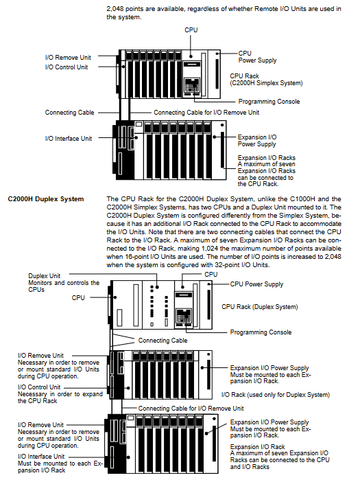
C2000H Simplex single CPU, supports hot swappable I/O 2048 points
C2000H Duplex dual CPU redundancy, automatically switches between 1024 points (16 point module)/2048 points (32 point module)
2. Rack composition
CPU rack: CPU unit+CPU power supply+I/O control unit+I/O unit
Expansion I/O rack: I/O interface unit+expansion power supply+I/O unit
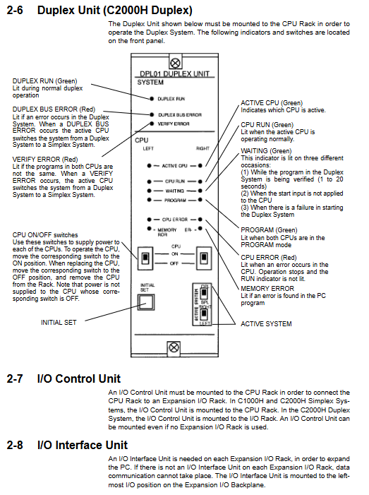
Duplex system: CPU rack (dual CPU+duplex unit)+independent I/O rack
Core hardware components
1. CPU power specifications
Model Input 5V Output I/O Available Current 24V Auxiliary
3G2A5-PS221-E AC100-240V 7A 4A/3A available
3G2A5-PS223-E AC100-240V 12A 9A/8A None
3G2A5-PS211-E DC24V 7A 4A/3A None
C500-PS213-E DC24V 9A 6A/5A None
2. I/O power specifications
Model Input 5V Output I/O Available Current 24V Auxiliary
3G2A5-PS222-E AC100-240V 7A 6.5A available
3G2A5-PS212-E DC24V 7A 6.5A None
3. Type of I/O unit
Input: DC24V, AC100-240V, AC/DC universal TTL
Output: Relay (2A), transistor (0.3~1A), bidirectional thyristor (1A)
Special I/O: AD/DA conversion, high-speed counting, positioning PID、PC Link
Installation and environmental requirements
Installation method
Must be installed vertically, with the CPU rack placed at the top
Rack spacing: 70~120mm
Expansion cable: maximum length of 2m per single cable, total length ≤ 12m
environmental parameters
Working temperature: 0~55 ℃
Humidity: 10%~90% RH (no condensation)
Anti vibration: 10~55Hz, 0.5mm, 2G
Wiring and grounding specifications
Grounding mandatory requirement
Grounding resistance: ≤ 100 Ω
Cable: ≥ 2mm ², length<20m
Independently grounded, not co grounded with the power system
Power wiring
AC: 100-120V/200-240V switchable
DC: 24V dedicated
Terminal torque: 1.2N · m
I/O wiring
Wire gauge: AWG22~18 (0.3~0.75mm ²)
Cold pressed terminals must be used
The distance between strong and weak electricity is ≥ 300mm
Safety and Protection
Mandatory Security
The emergency stop circuit must be implemented with external hardware
The forward and reverse rotation of the motor must be hardware interlocked
noise suppression
Inductive load parallel surge absorber/diode
Leakage current treatment: Input/output parallel discharge resistor
power-off processing
≤ 10ms: ignored
10-25ms: Possible shutdown
25ms: Stop output, power on automatically resumes
Maintenance and consumables
battery
Lifespan: 4 years (25 ℃)
Replacement: Within 1 week after the alarm, complete within ≤ 5 minutes
fuse
Specification: 3A/6.3A, 250V
The replacement must be completely powered off
relay
Lifespan: 300000 resistive cycles, 100000 inductive cycles
Key issues
Question 1: What is the core difference between C2000H duplex system and simplex system? How to achieve redundancy?
Answer: The duplex system adopts a dual CPU+duplex unit architecture, with one working and one standby, and switching without disturbance in case of failure; Single work refers to a single CPU. Duplex requires an independent I/O rack, with a maximum I/O of 1024/2048 points; Single work up to 2048 points, supports I/O hot plugging.
Question 2: What are the mandatory restrictions on the installation and expansion of this series of PLC racks? What problems will violating lead to?
Answer: It must be installed vertically, with the CPU on top and a rack spacing of 70-120mm. The single expansion cable should be ≤ 2m and the total length should be ≤ 12m. Violation can lead to insufficient heat dissipation, communication interference, I/O errors, and system instability.
Question 3: How to deal with leakage current and inductive load interference in I/O wiring? What are the risks of not handling it?
Answer: Input leakage current and discharge resistor, output leakage current and shunt resistor; Inductive load parallel surge absorber/diode. Not handling it can cause erroneous inputs, output loss of control, module breakdown, and system crashes.