Omron SYSMAC CPM2B series board PLC
The official operation manual (number W371-E1-03) of Omron SYSMAC CPM2B series board PLC covers the entire process of hardware specifications, installation and wiring, memory area, instruction system, analog module, programmer operation, debugging and fault handling. The core supports up to 168 point I/O, high-speed counting/pulse output, RS-232C/peripheral port dual communication, analog I/O expansion, with interrupt, synchronous pulse control, calendar clock function, suitable for embedded device control, clarifying safety specifications, wiring standards, programming steps, fault diagnosis, and is the authoritative basis for CPM2B installation, programming, debugging and maintenance.
Hardware specifications and system configuration
1. Core model and I/O
Type, Model, I/O Points, Power Supply, Output Type
CPU board CPM2B-32Cxx 32 point 12/24VDC relay/transistor
CPU board CPM2B-40Cxx 40 point 24VDC relay
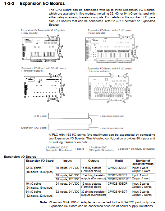
Expand I/O 32/40/64 points with up to 3 CPU powered relays/transistors
Analog MAD21/MAD42/MAD63 up to 3 24V CPU boards with 6 inputs and 3 outputs/4 inputs and 2 outputs/2 inputs and 1 output
Maximum configuration: 168 I/O points+8 analog inputs+4 analog outputs
2. Electrical specifications
Power supply: 12VDC (10.8~13.2V), 24VDC (20.4~26.4V)
Power consumption: maximum 20W
Impulse current: maximum 20A
Insulation: 1000VAC for 1 minute, insulation resistance 20M Ω
3. High speed function
High speed counter: 1 channel, 20kHz single-phase/5kHz two-phase
Interrupt input: 4 channels, response 50 μ s
Pulse output: 2 channels, 10Hz~10kHz (transistor type only)
Synchronous pulse control: Input 10-20kHz, output synchronous pulse
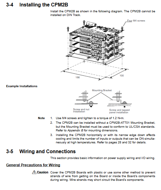
Installation and wiring specifications
1. Installation requirements
Method: Panel embedded installation, M4 screws, torque 1.2N · m
Environment: Temperature 0~55 ℃, humidity 10~90% RH, no condensation, no corrosive gas
Spacing: Maintain * * ≥ 200mm with heating equipment and strong electrical lines**
2. Mandatory wiring requirements
Power supply: Power off operation is required, use double insulated power supply
I/O line: separated from the power line, with a spacing of * * ≥ 300mm * *, using shielded wire
Terminal: Torque 0.5~0.6N · m, wire diameter 0.2~2.5mm ²
Safety: Emergency stop and interlock must be implemented through external hardware
Memory area allocation
Area size and purpose
IR 10 input/10 output word I/O mapping, working bit
SR 28 character system flag, current pulse value
HR 20 word power failure data retention
AR 24 word status flag, clock, error
LR 16 word 1:1 PLC link
DM 2048 word data storage, PLC settings, error logs
TC 256 point timer/counter
PLC settings: DM6600~DM6655, startup mode, communication, interrupt parameters
Error logs: DM2000~DM2021, up to 7 errors recorded
Instruction system
Basic instructions: 14 (LD, OUT, AND, OR, etc.)
Special instructions: 105 (MOV, CMP, TIM, CNT, PID, etc.)
Extension instructions: 35, can allocate 18 function codes
Execution speed: Basic instruction 0.64 μ s, special instruction 7.8 μ s
Analog I/O module
1. Model and specifications
Maximum number of connections for model input and output
MAD63 6:30:1
MAD42 4:2:02
MAD21 2:1:3
Signal range: 0~5V/1~5V/0~10V/-10~10V/0~20mA/4~20mA
Resolution: 6000 (full range)
Function: Wire breakage detection, average filtering
2. Key points for use
DIP switch: Switch voltage/current, turn on average value
Range codes: 000/-10~10V, 001/0~10V, 010/1~5V/4~20mA, 011/0~5V/0~20mA
Programmer operation
Supported models: CQM1H-PRO01-E, CQM1-PRO01-E, C200H-PRO27-E
Working mode:
Program: Programming, clearing memory, modifying settings
MONITOR: Monitoring, Mandatory, Online Modification
RUN: Running, only monitoring
Core operations: memory clearing, program reading and writing, instruction lookup, bit monitoring, forced set/reset
Debugging and troubleshooting
Self diagnostic function: CPU error, battery error, memory error, I/O bus error
Status light:
PWR: Power Supply
RUN: Run
ERR: Fault (constantly on fatal/flashing warning)
Common faults:
Unable to start: Check power, wiring, battery
Communication abnormality: Check baud rate, port mode, switch settings
Analog abnormality: Check DIP switch, range code, wiring
Key issues
Question 1: What is the maximum I/O and analog expansion capability of CPM2B? What are the restrictions?
Answer: The maximum digital I/O is 168 points, and it can connect up to 3 expansion boards at most; The maximum analog input is 8 inputs and 4 outputs. Only the 24V CPU board can connect analog signals, and MAD63 can only connect 1 block, MAD42 can connect 2 blocks, and MAD21 can connect 3 blocks.
Question 2: What scenarios are the three working modes of CPM2B used for? What are the precautions for mode switching?
Answer: Program is used for programming and setup; MONITOR is used for debugging and monitoring, and supports forced operations; RUN is used for official operation and modification is prohibited. Before switching, it is necessary to confirm the safety of the equipment, and emergency stop and interlock must be implemented by external circuits.
Question 3: How is the disconnection detection function of CPM2B analog module triggered? How to handle?
Answer: Only the 1-5V/4-20mA range supports wire breakage detection. It is triggered when the voltage is less than 0.8V or the current is less than 3.2mA, and the converted data is fixed at 8000; Automatically clear after restoring normal signal, no need for manual reset.