EPSON RC90/RC90-B Robot Controller
Epson RC90/RC90-B Robot Controller Hardware User Manual, compatible with EPSON RC+7.0 software, for LS series robotic arms, providing full process guidance on safety specifications, hardware specifications, installation wiring, mode operation, interface configuration, expansion board, backup upgrade, maintenance, and troubleshooting, emphasizing mandatory safety requirements such as dual circuit emergency stop, safety door interlock, power-off discharge, lock out/tagout, etc. It supports USB/Ethernet/RS-232C communication and I/O/fieldbus/analog/EUROMOP67 expansion, covering 4-axis servo control, status storage, firmware upgrade, scheduled maintenance, and complete error code table. It is the core basis for robot system installation, debugging, and operation and maintenance.
Core security standards (mandatory requirement)
Emergency stop system
Adopting dual redundant normally closed contacts, any emergency stop press immediately cuts off motor power
The safety door input has the same dual circuit, and if the difference is greater than 2 seconds, a serious fault will be reported
Power off operation
After power failure, wait for at least 10 minutes to confirm that the busbar discharge is complete before proceeding
maintain safety
Lockout/Tagout must be executed to prevent accidental power on
Only for trained personnel to operate
Hardware specifications
Project parameters
Control axis number 4-axis AC servo
Power supply single-phase 200-240VAC, 50/60Hz
Maximum power consumption of 2.5kVA
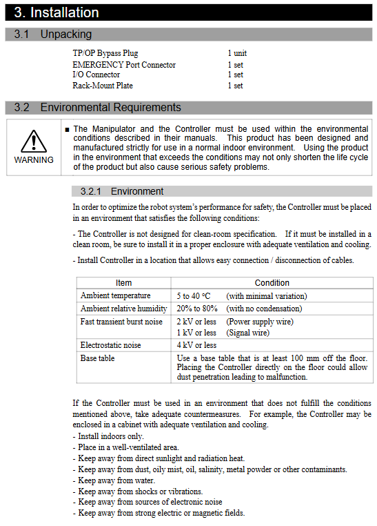
Working temperature 5-40 ℃
Humidity 20-80% RH (no condensation)
Weight 7.5kg/10kg (depending on the model)
Protection IP20
Panel and Interface
Status LEDs: ERROR, E-STOP, TEACH, AUTO, GRAM
standard interface
USB: Connect and debug PC
LAN: 10/100M, default IP 192.168.0.1
RS-232C: Standard 1-port, expandable
TP: Teaching pendant port (must be connected to TP or short circuiting cap)
EMERGENCE: Emergency Stop+Safety Door+Latch Unlock
I/O: 24 in/16 out
Three operating modes
TEACH mode
Teaching demonstration, jog, low speed and low power consumption, safety door can be opened for operation
AUTO mode
Automatically running programs, supporting remote I/O start and stop
Program mode
Programming, debugging, parameter configuration
I/O and Remote Control
Standard I/O: 24 in/16 out
Default allocation for remote I/O
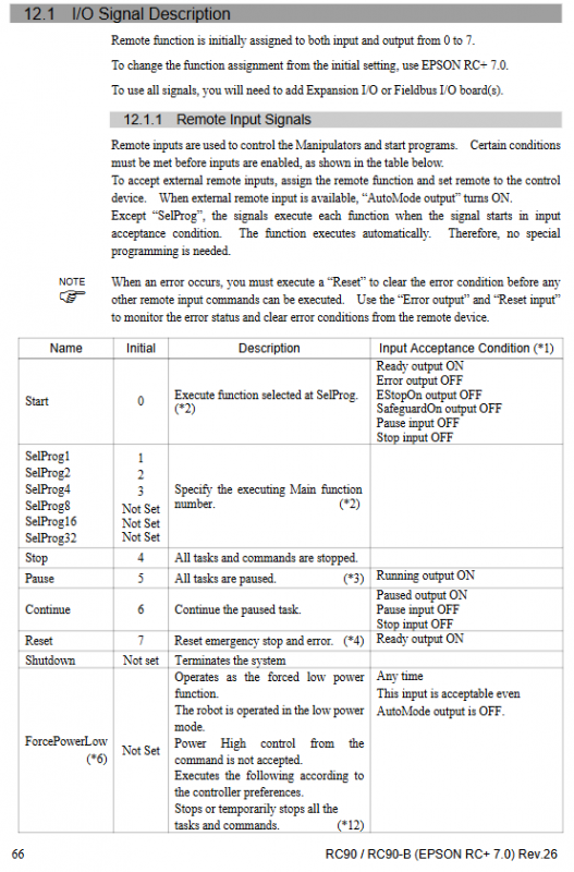
Input: Start, Stop, Pause, Reset, SelProg
Output: Ready, Running, Error, EStopOn, SafeguardOn
Signal pulse width requirement: ≥ 25ms to be recognized
Optional expansion board (up to 2 pieces can be installed)
Expansion I/O board: Add 24 inputs/16 outputs per board
Fieldbus board: DeviceNet, PROFIBUS, PROFINET, EtherCAT, CC Link
Analog I/O board: 16 bit precision, 0-10V/4-20mA
EUROMOP67 board: Injection molding machine interface, 15 in/16 out, with safety circuit
Backup, Recovery, and Firmware Upgrade
Backup content
Parameters, programs, point data, global variables, configurations
backup method
EPSON RC+7.0 Backup Controller
USB storage: One click save with Trigger on the front panel
Upgrade requirements
Must be connected via USB, network port not available
Upgrade without power outage or unplugging cables
Recovery mode
Press and hold Trigger to power on → enter Recovery → refresh firmware
Regular maintenance
Performance of Component Maintenance Cycle Malfunctions
Fan dust filter screen cleaned monthly, overheating, error 514/515
Fan abnormal noise replacement error 9015
The battery reports 511 parameter loss and needs to be recalibrated every 5 years with errors
CF card failure, immediate replacement, unable to start, file error
Fault diagnosis
LED judgment
E-STOP on: Emergency stop pressed/circuit disconnected
ERROR on: Fault; Flashing: Warning
Typical Error
511: Low voltage of CPU board battery
514: Internal overheating of the controller
515: Fan speed too low
1041: Unable to operate in emergency stop state
1042: The safety door is open
Key issues
Question 1: Why does the emergency stop and safety door of RC90/RC90-B require dual circuit wiring? What will happen if I make a mistake?
answer:
The emergency stop and safety door adopt dual redundant independent circuits, and any fault system in either circuit can be detected and alarmed; If the difference between the two states exceeds 2 seconds, it will trigger a serious safety fault and shut down.
Consequences of incorrect connection: inability to release emergency stop normally, failure of safety interlock, robot inoperability, posing serious safety risks.
Question 2: What data can be stored in USB Controller Status Storage? What should I pay attention to when restoring?
answer:
Save contents: controller parameters, robotic arm parameters, programs, point data, error history, I/O configuration, global variables.
Notes:
Only supports USB 2.0 unencrypted USB flash drives
Do not turn off the power when saving
Recovery can only be used for controllers with the same serial number, otherwise an error will be reported
After recovery, a restart is required to take effect
Question 3: What is the function of EUROMOP67 board? What are the key points of wiring?
answer:
Function: Provide standard interfaces between injection molding machines and robots to achieve mold cavity signals, mold opening and closing, ejector pin, and safety linkage.
Key points of wiring:
Emergency stop and safety circuits must be connected in both directions
Signal voltage * * ≤ 24V * *, otherwise the board will be burned out
I/O logic confirmation based on injection molding machine model
Shielded wire is grounded at both ends to reduce interference