Beckhoff EL70x7 series stepper motor EtherCAT terminal manual
Product Overview (EL7037&EL7047)
The EL70x7 includes two core models, both of which are single channel stepper motor EtherCAT motion terminals, supporting vector control, incremental encoder, and 64 subdivision micro steps, distinguishing voltage, current, and power levels.
1. Comparison of core parameters
Parameter item EL7037 EL7047
Rated power supply 24VDC (-15%/+20%) 8-48VDC
Output current (fanless) 1.5A 5A
Output current (equipped with ZB8610 fan) 3.0A 6.5A
Application positioning: Small power stepper motor, medium power stepper motor
Dimensions 15mm x 100mm x 70mm (installation width 12mm) 27mm x 100mm x 70mm (installation width 24mm)
Weight approximately 60g, approximately 105g
E-Bus power consumption typical 100mA typical 140mA
Encoder maximum pulse 400k/s (4th harmonic) 400k/s (4th harmonic)
Step frequency options include 1000/2000/4000/8000/16000 full steps per second, same as left
Microstep up to 64 times (automatically switches with speed) up to 64 times
Electrical isolation 500V (E-Bus and signal side) 500V
Working temperature: 0 ℃~+55 ℃, storage: -25 ℃~+85 ℃, same as left
Protection level IP20 IP20
Certification CE, EAC, UKCA, cULus on the same left
2. General hardware configuration
Interface: 2-channel limit digital input, 1-channel configurable brake output (0.5A), incremental encoder interface (A/B/Z phase+latch);
Drive characteristics: The current loop frequency is about 30kHz, and the output has overload, short circuit, and over temperature protection;
Wiring method: screw free spring terminal, compatible with 0.08-2.5mm ² cables;
Indicator lights: power, operation, encoder, motor phase fault, alarm, enable, steering and other status LEDs for intuitive diagnosis.
Principles of Core Control Technology
EL70x7 provides three control modes, adapted to different motors and application scenarios, with the core focus on optimizing stepper motor drive.
1. Fundamentals of stepper motor
The equipment is compatible with two-phase hybrid stepper motors (mainstream in industry), and the motor parameters (step angle, inductance, back electromotive force, moment of inertia, cogging torque) directly affect the operational stability. The document provides a complete process for motor selection, parameter calculation, and load matching.
2. Three major working modes
(1) Standard mode (universal type)
Adaptation: All two-phase stepper motors (third-party/Beifu motors are acceptable);
Principle: Sine/cosine current drive, up to 64 sub steps, traditional stepper drive architecture;
Features: Excellent dynamic performance and low cost; The disadvantage is that it is prone to resonance at low speeds and easy to lose steps when unloaded.
(2) Magnetic field directional control (extended mode)
Limitation: Only supports Beifu AS10xx series stepper motors, requiring an incremental encoder (minimum 4000 pulses/rev);
Principle: Decoupling excitation and torque current through Parker transformation, equivalent stepper motor to servo motor;
Advantages: Thoroughly eliminating resonance, preventing step loss, load adaptive current reduction, significantly reducing power consumption and heat generation, dynamically approaching servo;
Pre requirement: Perform commutation calibration (slight forward and reverse rotation of the motor) when powering on.
(3) Sensorless mode
Limitations: Only supports Beifu AS10xx motors, no encoder required;
Principle: By detecting the back electromotive force of the motor, the speed and load are estimated to achieve load adaptive current control;
Operating rules: Automatically switch to standard mode at low speed, and enable sensorless control after reaching the set switching speed;
Features: Save encoder costs, high energy efficiency; The disadvantage is a slight decrease in dynamic performance and slight mechanical shaking during switching.
3. Auxiliary functions
Microstep: up to 64 times subdivision, automatically switches with speed, improves positioning accuracy and smooth operation;
Load angle detection and out of step detection: Fault diagnosis can be achieved through encoder/back electromotive force;
Torque load reduction: Automatically reduce motor current and minimize heat generation when stationary.
EtherCAT Communication Fundamentals
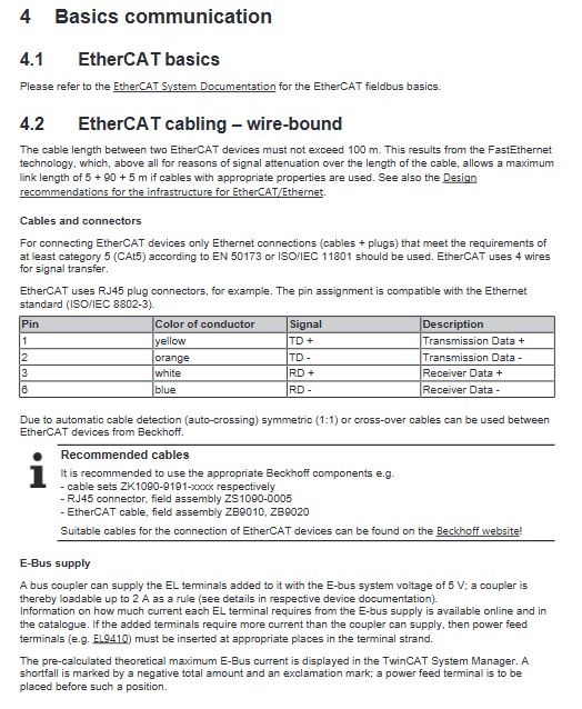
1. Hardware wiring requirements
Cable: Use Cat5 and above Ethernet cables, with a maximum cable length of 100m between devices, and use RJ45 interfaces;
Wiring: Only 4 network cables are used for signal, supporting direct/cross connection (automatic recognition);
E-Bus bus: The maximum output current of the bus coupler is 2A. When the current is insufficient, EL9410 and other feeding terminals need to be installed, and all terminals must be grounded together.
2. Watchdog
The device is equipped with SM synchronization manager watchdog and PDI process data watchdog (default 100ms), which automatically set the output to a safe state when communication is interrupted. The timeout can be configured in TwinCAT.
3. EtherCAT state machine
Standard 5 operating states, switch sequentially when powered on:
Init: Initialization, no communication;
Pre op: Email communication available, no process data available;
Safe op: The process data communication is normal, and the output is locked in a safe state;
Op: Normal operation, fully functional enabled (main working state);
Boot: Dedicated for firmware upgrade, prohibited for normal use.
4. CoE interface (CANopen over EtherCAT)
Function: Device parameter configuration, reading and writing diagnostic data, parameter management in the form of index+sub index (hexadecimal);
partition
0x1000 segment: read-only information such as device identity, version, serial number, etc;
0x6000/0x7000: Process Data PDO;
0x8000 segment: motor, control core parameters (read-write);
Data storage: Supports NoCoeStorage function, which can turn off parameter power-off saving to avoid frequent EEPROM erasure and damage;
Startup list: Pre stored parameters, automatically loaded when the device is powered on, no need to reconfigure when changing terminals.
5. Distributed Clock (DC)
EtherCAT distributed clock, synchronization accuracy<100ns, unit 1ns, meets the requirements of multi axis synchronous motion.
Installation and wiring specifications
1. Mechanical installation
Rail: Standard 35mm DIN rail, rail must be reliably grounded;
Disassembly and assembly: The terminal has an orange unlocking buckle, which can be pushed and pulled to unlock after power failure. Hard breaking is prohibited;
ESD protection: Grounding before operation, do not touch the spring, EL9011/EL9012 end caps need to be installed at the end of the bus;
Installation posture: Horizontal installation without fan, bottom ventilation, with a reserved space of ≥ 20mm above and below; After installing the fan, it can support other installation angles;
Mechanical strength: In high vibration scenarios, it is necessary to fix the guide rail and limit the length of the terminal string to meet the EN 60068 vibration/impact standard.
2. Wiring rules
Power supply requirements: SELV/PELV safety ultra-low voltage power supply must be used, and the load circuit must also comply with SELV specifications;
Motor wiring: Strictly distinguish between A1/A2 and B1/B2 two-phase windings, and prohibit cross phase wiring, otherwise the drive will be burned out; Support single/bipolar stepper motors;
Shielding: Encoders and signal lines must use shielded twisted pair cables, and the shielding layer must be grounded at a single point;
Fuse: The load circuit fuse needs to limit the short-circuit current to 3 times the rated current (up to 1 second);
Braking treatment: For short deceleration slope conditions, EL9576 brake chopper is required to absorb feedback energy.
3. Terminal pins and LED
EL7037/EL7047 respectively define the encoder, motor, limit, and power pins. Detailed pin diagrams and wiring examples are attached to the document;
LED status: distinguish between operation, encoder, power supply, enable, warning, phase fault, etc. The red light represents hardware fault, the yellow light is alarm, and the green light is normal status.
4. Waste disposal
The equipment belongs to electronic waste and must be recycled in accordance with local electronic waste regulations. It is prohibited to dispose of it indiscriminately.
TwinCAT Configuration and Debugging (Core Operations)
Compatible with both TwinCAT 2 and TwinCAT 3 versions, supporting offline configuration (pre configuration) and online scanning (automatic hardware recognition) modes.
1. Pre preparation
Real time driver: TwinCAT real-time Ethernet driver needs to be installed on the PC network port to distinguish between correct and incorrect driver configurations;
ESI file: EtherCAT device description file, needs to be updated in a timely manner, TwinCAT has built-in ESI upgrade tool;
Offline/online distinction: offline=no hardware pre programming; Online=Scan configuration after connecting hardware.
2. Configuration process
Add EtherCAT device: Add an EtherCAT master station to the I/O device and bind the network card;
Scanning terminal: automatic recognition of EL7037/EL7047 in online mode, manual selection of equipment model and revision offline;
PDO configuration: predefine multiple process data schemes (speed control, position control, positioning interface, etc.) and select them as needed;
NC axis integration: Associate terminals with TwinCAT NC axis to achieve servo positioning control (supporting point positioning and continuous motion).
3. Core parameter configuration (CoE register)
Basic parameters of the motor: rated voltage, coil resistance, inductance, back electromotive force, number of steps, encoder resolution;
Control parameters: maximum current, static current reduction, step frequency (speed range), feedback type (internal counting/external encoder);
Control loop parameters: current loop, speed loop, position loop PID;
Calibration of NC axis parameters such as scaling factor, reference speed, tracking error, and dead zone.
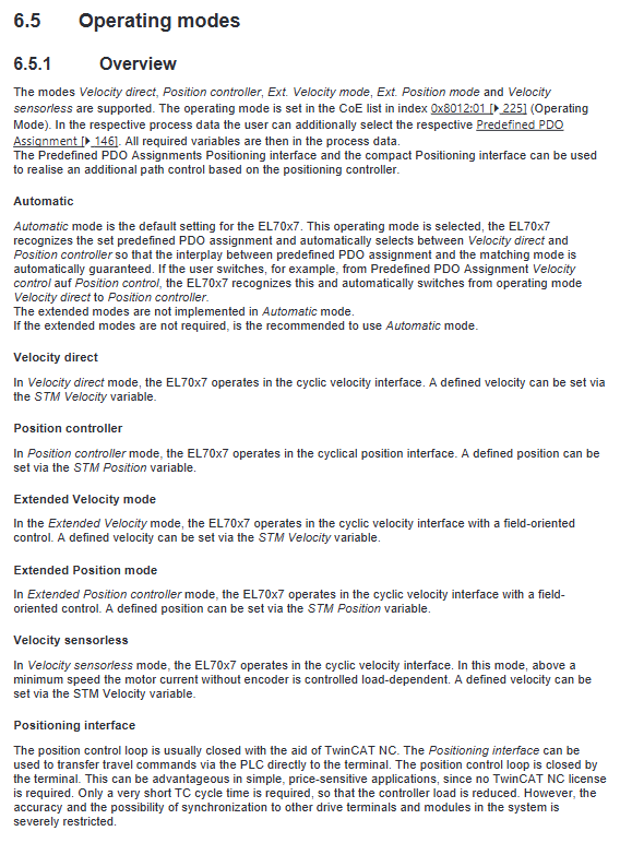
4. Five major operating mode configurations (CoE 0x8012:01 selection)
|Operating mode | Motor adaptation | Encoder requirements | Core features|
|Auto mode (default) | All | Optional | Automatically switches speed/position mode, recommended for regular use|
|Direct Speed Mode | All | Optional | Loop Given Speed, Dynamic Good|
|Position Controller Mode | All | Optional | Loop Given Position for Positioning|
|Extended speed mode | Beifu AS10xx | Required | Vector control, low resonance, energy-saving|
|Extended Position Mode | Beifu AS10xx | Required | Vector Positioning, No Out of Step|
|Sensorless speed mode | Beifu AS10xx | No need | Save encoder, running at medium to high speeds|
5. Programs and Cases
Support IEC 61131-3 full programming languages (ST, LD, FBD, etc.);
Provide complete routines: including axis enable, jog, absolute positioning, speed operation, status monitoring, with a visual interface;
When NC authorization is not required, a positioning interface can be used to locally loop the terminal and reduce the controller load.
Fault diagnosis and maintenance
1. Diagnostic system
LED diagnosis: Quickly diagnose power supply, enable, phase short circuit/over temperature, and encoder faults;
Process data diagnosis: reading axis status, tracking error, load, synchronization error, etc;
CoE diagnostic register: View detailed fault codes, temperature, and operating data.
2. Common faults
Communication failure: Check the network cable, EtherCAT state machine, and watchdog configuration;
Motor malfunction: overheating, short circuit, phase loss, out of step, resonance;
Encoder malfunction: pulse loss, wiring error, abnormal counting.
3. Firmware and Maintenance
Firmware upgrade: distinguish between controller firmware (. efw) and FPGA firmware (. rbf), support batch upgrade for single/multiple devices;
Factory reset: Restore the default parameters of the device through the CoE register;
Spare parts compatibility: High revision versions of equipment can directly replace lower versions.