Beckwith M-3311 Transformer Protection Relay
Product positioning and application scenarios
1. Core protected objects
Two winding and three winding power transmission and distribution transformers;
The complete set of differential protection for the generator set and transformer set;
Protection of busbars and other electrical equipment units within the station (including busbars with transformers within the area).
2. Expand auxiliary applications
System backup protection, voltage/frequency logic load shedding, busbar protection, independent circuit breaker failure protection for each winding; It can be used in conjunction with feeder relays to achieve feeder backup tripping, voltage tap changer LTC fault lockout, and external temperature controller linkage monitoring.
3. Hardware input configuration restrictions
Only supports 1 single-phase voltage input, choose one wiring mode: phase voltage (for 24/27/81O/U) or open delta PT (only 59G grounding overvoltage, two types of voltage functions are mutually exclusive);
There are a total of 11 CT current inputs, and the grounding differential current input is compatible with 2/3 windings;
Optional single-phase voltage protection package to expand voltage protection functions.
Standard protection function as standard (ANSI standard number, with complete set parameter table)
All protection windings are independently configured, supporting 1A/5A CT secondary ratings. The parameters include setting range, adjustment step size, and accuracy (the accuracy is taken as the larger error value between the two indicators, with the 1A CT dedicated interval in parentheses):
46 Negative sequence inverse time overcurrent (W2/W3 winding)
Divided into time limit and inverse time limit, with built-in Beco/IEC multi class inverse time limit curves to cope with three-phase unbalanced faults.
49 winding thermal overload protection
Optional W1/W2/W3 single winding input, set the thermal time constant and maximum overload current, and only allow one winding to be put into operation at a time.
50 Three winding instantaneous phase overcurrent
Each winding has dual independent components, which can be set with action current and delay respectively, and instantaneous/timed limits are optional.
50BF circuit breaker failure protection
Separate phase current criterion and residual zero sequence current dual criterion, with independent delay configuration for each winding.
50G instantaneous grounding overcurrent, 50N instantaneous residual zero sequence overcurrent
Each winding has independent fixed values for dual components, suitable for winding grounding and neutral point zero sequence faults.
51 Three winding inverse time phase overcurrent, 51G inverse time grounding overcurrent, 51N inverse time remaining zero sequence overcurrent
Rich standard inverse time curve library, customizable time scale, as a backup protection for phase to phase and grounding.
87T three winding transformer differential main protection+87H differential quick break
Dual slope braking characteristics and adjustable inflection point; 2/4th harmonic excitation surge braking, 5th harmonic overexcitation braking; CT ratio compensation; When the tripping speed is less than 1.5 cycles after a delay of 1 cycle, each braking component can be individually activated or deactivated.
87GD grounding differential protection
Equipped with directional discrimination logic, the directional function automatically exits when the zero sequence current is extremely small; The recommended delay is not less than 2 cycles and supports CT ratio correction.
EXT 1-6 six external expansion logic functions
External contact point triggering, custom delay, can be linked in and out, combined with BECO Logic to achieve third-party device linkage tripping and fault alarm.
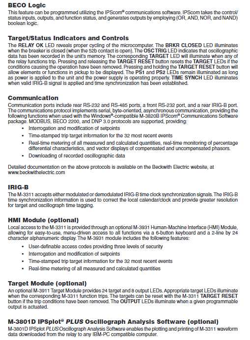
BECO Logic Programmable Boolean Logic
Support and/or and non/or non arithmetic operations, combined with input, protection action signals, and output to achieve custom interlocking, locking, and constant value switching logic.
Circuit breaker wear monitoring
Integrate It/I ² t to calculate the total amount of phase separated arc burning, output an alarm for exceeding the limit, and the value can be viewed locally.
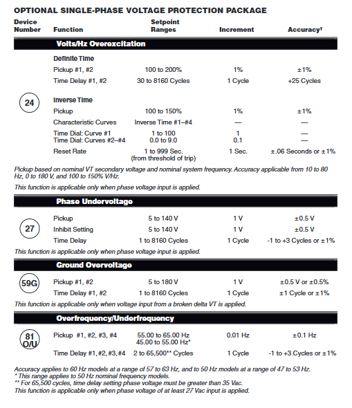
Optional single-phase voltage protection package (optional, must be connected to PT voltage input)
The voltage function is limited by a single voltage input, and the phase voltage and open delta function are mutually exclusive:
24 V/Hz overexcitation protection: 2 fixed time limits+1 reverse time limit to suppress transformer core demagnetization;
27 phase undervoltage protection: used for system low-voltage load shedding logic, with closed locking value;
59G zero sequence grounding overvoltage: only open delta PT wiring is available, monitoring system grounding fault zero sequence voltage;
81O/U over/under frequency protection: 4 sets of independent frequency components, 50/60Hz system corresponding to different setting intervals, input voltage ≥ 27Vac can be put into operation.
General functions of standard hardware for the entire machine
Multi group constant value area: 4 sets of independent constant values, supporting panel manual, communication, and input signal switching, adapting to multiple operating modes of the system.
IO circuit (fixed without expansion module)
6-channel programmable state input: passive dry contact, internal 24V wet contact, operating current ≥ 25mA; IN1 connected to the auxiliary contact drive panel closing indicator light of the circuit breaker with a circuit breaker with a circuit breaker with an auxiliary contact; Can be locked for protection, trigger waveform recording, and switch to a fixed value group.
8-channel programmable output: 1-6 normally open (Form A), 7/8 conversion contacts (Form C); 1-4 output high-speed action, 4ms faster than 5-8; customizable protection driver for any output.
Power alarm normally closed and self-test alarm conversion contacts are standard.
Fault storage and waveform recording
Target fault storage: up to 32 sets of fault records can be saved, including action components, time scales, current, and contact status;
Oscillographic recording: Sampling rate 16 times the power frequency, up to 152 cycles waveform, supports 1-4 storage partitions, pre trigger+post trigger recording, exports to COMTRADE format, matched with M-3801D IPSplot PLUS analysis software;
Real time measurement function
Measure three-phase voltage, phase/zero sequence current, frequency, and sequence components; Support real-time demand of 15/30/60 minutes and maximum demand with time stamps; The document specifies the accuracy indicators for voltage, current, and frequency measurement.
Communication interface (standard)
Front panel RS232, back panel dual RS232+RS485; IRIG-B clock synchronization (modulation/demodulation dual standard); Native support for MODBUS, BECO2200, DNP3.0 serial port protocols; Equipped with the upper software M-3820B IPScom, it realizes constant value reading and writing, waveform recording download, event reading, and real-time phasor monitoring.
Human machine and status indicator lights
RELAY OK, BRKR CLOSED, OSC TRIG, PS1/PS2 power supply, TIME SYNC synchronization indicator light; TARGET RESET button, long press to view the current action component.
Hardware basic design
Standard 19 inch rack with a height of 3U; The PCB and power module are detachable; Provide 50Hz/60Hz models; CT secondary 1A/5A optional; Optional redundant power supply.
Optional external accessory module
M-3931 HMI human-machine interface module: 2-line 24 character LCD, 6 buttons, 3-level permission password, local constant value modification, measurement, fault query;
M-3911 Target fault indicator module: 24 fault LEDs+8 output status LEDs, visually displaying protection trip components;
M-3801D IPSplot PLUS waveform analysis software: computer side analysis, printing of recorded COMTRADE files;
Redundant power module.
Input circuit hardware electrical parameters
Voltage input (1 channel): rated 60~140Vac, long-term withstand voltage 240V, short-term 360V/10s, PT load < 0.2VA;
CT current input (11 channels): 5A/1A optional, long-term withstand 3 times rated, 1-second withstand 100 times rated; 5A model CT load<0.5VA, 1A model<0.3VA;
Open circuit: External voltage is prohibited, only dry contacts are allowed to be connected, otherwise the device will be damaged;
Output contact capacity: Complies with IEEE C37.90 and UL508 standards, providing parameters for AC/DC breaking and carrying current.
Power specifications
Communication: 85~265Vac, DC 80~288Vdc (110/120/230/240Vac, 110/125/220/250Vdc nominal);
Low voltage DC: 18~56Vdc (24/48Vdc nominal);
Power consumption of 20VA, with a 1-second short-time overvoltage tolerance index; Optional redundant power supply.
Safety regulations, electromagnetic compatibility, and environmental mechanical standards
1. Insulation withstand voltage and impulse (IEC 60255-5)
AC/DC withstand voltage, 5kV lightning impulse, insulation resistance>40M Ω;
2. EMC electromagnetic immunity
ESD static level 4, 4kV fast transient, IEEE C37.90.1 surge withstand, 25-1000MHz radiation immunity;
3. Working environment
Operating temperature -20 ℃~+70 ℃; Storage at 5-40 ℃; Up to 93% RH without condensation;
4. Mechanical endurance
Vibration and impact comply with IEC 60255-21 series Class1 level;
5. Product certification
CULus 508 industrial equipment, Canadian CAN/USA C22.2, CE certification.
Physical dimensions, installation, and wiring
Horizontal standard rack: 19 inches wide x 5.21 inches high x 10.20 inches deep (48.3 x 13.2 x 25.9cm), net weight 7.7kg; supports ANSI/EIA RS-310C, DIN 41494 industrial rack;
Optional vertical panel installation, with hole size diagram included in the document;
Terminal wiring specifications: Cable specifications # 22~12AWG copper core, divided into two terminal torque requirements, strictly prohibited from damaging the terminals due to excessive torque; Output 1-4 with high-speed trip circuit;
Supporting multiple sets of typical primary single line diagrams: application wiring schemes for three winding transformers, dual unit generator transformer sets, three winding transformers with parallel reactors, and ring network substations.