DEIF AGC200 Quick Start Guide
List of Supply Accessories
Standard configuration
AGC200 controller host;
AGC20 Complete Installation Manual (including terminal diagram, IO list, and standard wiring diagram).
Optional accessories
J4/J7 PC communication cable: used for local debugging of computer USW software;
AOP-2 External Operation Panel (X4 Option): Remote operation and monitoring of the unit, wiring reference to the corresponding option manual.
Introduction to Power on and Wiring (Core Practical Chapter)
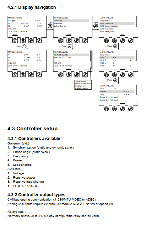
Four typical application basic wiring diagrams
The manual provides key terminal wiring diagrams for four mainstream operating conditions, indicating the core points of DC power supply, voltage and current sampling, circuit breaker relay, and communication port:
Single standalone mode: Single unit, generator circuit breaker GB, mains circuit breaker MB output relay; Standard configuration includes Modbus, load sharing CAN bus interface, and 8-32V wide DC power supply.
Island Island Operation Mode: No mains power collection circuit, only bus voltage and generator sampling, only GB closing and opening output.
Mains grid connection mode: Simultaneously collect mains and generator voltages, equipped with MB (mains switch) and GB (generator switch) dual control relays, supporting grid synchronization.
BTB bus connection mode: dual bus acquisition, equipped with a contact circuit breaker BTB control output, used for the scenario of two bus sections switching to each other.
Unified hardware common terminal: DC positive and negative power supply, Modbus RTU communication, CAN load sharing bus, three-phase CT current acquisition, PT voltage acquisition, multi-channel programmable relay output.
DEIF USW upper software installation and connection process
Software download channels
Log in to the DEIF official website → Document Software section;
Select the Multi line 2 series USW3 tool and fill in your email to receive the download link for installation.
USB driver installation
Vista/Win10 and above: automatic installation of drivers;
Windows XP: Pop up the hardware installation wizard twice, select recommended automatic installation; Select ‘Continue Installation’ in the unverified pop-up window of the system, and the default driver path is C: \ Program Files \ DEIF \ USW3 driver folder.
Equipment connection steps
Connect the controller service port to the computer USB using J3/J7 debugging cables;
Open the USW software and check the device manager to confirm the COM port. The port parameters in the software match;
Click on the software connection icon to establish communication and read all parameters of the controller online.
Basic parameter configuration operation
Read the parameters of the entire machine and upload them to the software;
Switch to the ‘Gen’ unit configuration tab and modify key parameters such as rated voltage and frequency;
Pop up window to modify the set value, click on write and confirm to send to the controller;
Refer to the official debugging general guide for deep debugging.
Display Panel Buttons, LEDs, and Controller Adjustment
Panel button function (20 physical buttons in total)
Measurement view, event log (storing 150 lost power outages), parameter settings, service diagnostics;
Navigation up, down, left, right, alarm mute, return exit, lamp self check, test mode;
Operation mode switching: semi-automatic, shutdown, manual, automatic;
Circuit breaker operation: mains power on/off, generator on/off;
Unit start stop button (only valid in semi-automatic/manual mode).
Status LED indicator light (red green dual color)
Custom indicator lights;
Power light: Constant light indicates that the auxiliary power supply is normal;
Alarm light: flashing=unconfirmed alarm, constantly on=alarm confirmed but fault still exists;
Operation mode indicator light: shutdown/semi-automatic/manual/automatic independent indication;
Mains OK light: green normal, red mains fault, flashing=mains recovery delay countdown;
MB city power closing and GB generator closing status lights;
Unit voltage frequency normal indicator light;
Unit operation feedback indicator light.
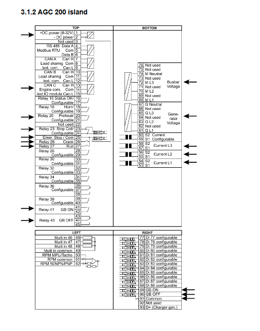
Menu navigation logic
Panel layered menu: protection, synchronization, adjustment, digital input, service menu; Support jump shortcut keys to view real-time measurements, alarm timing, input/output status, and event timestamps.
Types and output modes of built-in regulators
1. Standard adjustment controller
Speed regulation GOV: frequency, active power, load sharing, dynamic/static synchronization, phase adjustment;
Voltage regulation AV (standard): voltage, reactive power, power factor, and reactive power sharing.
2. Control output channels
Relay output (standard configuration, programmable relays 28~34);
0/4-20mA analog output (requires IOM200 expansion module/H8 option);
CAN engine bus (supporting J1939 and MTU dedicated engine communication protocols).
3 AVR+speed regulation complete setting process
The manual provides a standardized configuration flowchart: select AVR/speed control relay, set rated frequency/voltage, set PI proportional integral parameters, ramp time, minimum pulse duration, switch between semi-automatic/automatic mode to complete the adjustment and enable.