ADLINK cPCI-6520 6U CompactPCI Single Board Computer
Product Overview
1. Core hardware platform
-Processor: Third generation Intel Core i7 22nm mobile series quad core/dual core FC-BGA SoC, available in four options:
I7-3615QE (4-core 45W), i7-3612QE (4-core 35W), i7-3555LE (dual core 25W), i7-3517UE (dual core 17W), supporting turbo frequency, hyper threading, and virtualization VT-x/VT-d;
-Chipset: Mobile Intel QM77 PCH;
-Memory: Dual channel ECC DDR3, onboard soldering up to 8GB+SO-DIMM slot up to 8GB, machine maximum 16GB;
-Form: 6U 4HP single slot CompactPCI, supporting two working modes of system main control slot/peripheral satellite slot, compatible with PICMG2.0/2.1/2.9/2.16 full series cPCI specifications.
2. Board core interface resources
1) Display output
Front dual DP dual channel display (convertible to DVI/VGA/HDMI); Rear independent VGA/eDP, up to 3 screen outputs; If DP is converted to DVI/HDMI, the rear display will be disabled.
2) Network
Front mounted 2 Gigabit Intel 82579LM/82574L Ethernet ports; After matching with RTM, the adapter module can be expanded to two additional gigabit channels and supports PICMG2.16 packet switching backboards.
3) Serial port
Front RJ45 COM1 (RS232/422/485 three mode dial code); Rear mounted two serial ports, with a maximum of three serial ports for the entire machine.
4)USB
Front mounted 3-channel USB 3.0; RTM backplane expansion with 6 USB 2.0 channels and 1 USB 3.0 channel.
5) Storage
Onboard standard CF card slot; Optional DB-LSATA daughter card installation with 2.5-inch SATA SSD; Optional DB CFast adapter card (mutually exclusive with SATA, choose one), SATA speed 6Gb/s.
6) Expand sub card
Single PMC/PCIe x8 XMC mezzanine expansion slot, using PI7C9X130 bridge chip to achieve PCIe to PCI-X expansion.
7) Security module
Optional Atmel AT97SC3204 TPM hardware encryption chip, supporting SHA1, 2048 bit asymmetric encryption, voltage/frequency tamper proof, and memory encryption.
8) System peripherals
PS/2 keyboard and mouse, HD audio, 8-channel general-purpose GPIO, hardware watchdog, IPMC chassis management, 3V button RTC battery.
3. Matching RTM adapter module series
|Model | Extended Resources|
| cPCI-R6002 | DVI、 2 serial ports, 3 USB, 2 Gigabit, 2 SATA|
|CPCI-R6002D | 8HP Widening, Audio PS/2、 More USB|
|CPCI-R6100 | 4 Gigabit Ethernet CF/SD、VGA |
|CPCI-R6200 | 8-channel mini SAS hardware RAID, multi-channel serial port USB|
|CPCI-R6700/6700D | Onboard ATI E4690 discrete graphics card, dual DVI output|
4. Power supply specifications
Only supports cPCI backplane+5V main power supply, auxiliary 3.3V, ± 12V; voltage tolerance: 5V ± 5%, 3.3V ± 5%, ± 12V ± 5%; Provide four types of CPUs with full load/idle power consumption, with the lowest being dual core 17W at full load, only 43.6W, and quad core 45W at full load, 77W.
5. Environment and reliability
-Standard operating conditions: forced air cooling at 0-60 ℃; Wide temperature ET version -20~70; EX ultra-low temperature version -40~85 (only low-power dual core CPU);
-Storage: -40~85 ℃; Humidity of 5%~95% without condensation;
-The impact vibration complies with MIL-STD-202F; The whole machine has a high MTBF and is suitable for military, communication, and industrial measurement and control.
6. Operating system support
Windows7 32/64、Windows Server2008 R2、RedHat/Fedora Linux、VxWorks 6.9, Comes with a complete driver package.
Detailed hardware specifications
1. Characteristics of processor core
The entire system supports 64 bit, hyper threading, Turbo 2.0, SpeedStep energy-saving, VT-x/VT-d virtualization, TXT trusted execution, and AES hardware encryption; Four core 6MB cache, dual core 4MB, with a maximum single core turbo frequency of 3.3GHz.
2. QM77 chipset capability
Supports multiple generations of USB, 6-way SATA (2-channel 6Gbps), PCIe 2.0, HD Audio, AMT active remote management, SMBus system management, and ACPI4.0 power management.
3 PMC/XMC expansion slots
– PMC:32/64bit PCI-X,33/66/133MHz, Jumpable switch between 3.3V/5V IO levels;
-XMC: PCIe x8 Gen3 high-speed mezzanine card, high-speed data acquisition, graphics acceleration expansion.
4. AMT remote management
Hardware out of band management allows remote reading of hardware status, power on/off, system configuration, and troubleshooting in shutdown/fault states, without the need for operating system support.
5 TPM security chips
Hardware encryption, anti physical cracking, voltage and frequency abnormal lock key, meet the information security requirements of industrial control/network security equipment.
Board layout, connectors, and dip switches
1. Front panel interface
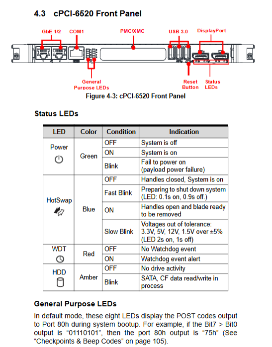
Dual DP, 3xUSB3.0, RJ45 multifunctional serial port, PMC/XMC slot, reset button, status LED: power supply, hot swappable, watchdog, hard disk read-write, 8-bit POST diagnostic light.
LED Description: Power green, hot swappable blue, watchdog red alarm, amber hard drive activity light.
2. Classification of onboard connectors
1. cPCI standard J1/J2/J3/J4/J5 backplane connectors: carry PCI bus, IPMC chassis management, and rear IO (network/serial/USB/audio/display/SATA/GPIO) respectively;
2 Front end peripherals: DP, USB, RJ45 serial port;
3 onboard internal components: SATA, CF, CFast, PMC/XMC, RTC battery, fan GPIO;
4 Debugging: DB40 low-level debugging port, JTAG factory debugging.
3 Key DIP Switch Functions
1 SW1: One click restore BIOS factory default;
2 SW12: COM1 serial port mode switching (RS232 default/422/485);
3 SW_SOD1: IPMC chassis management with or without chassis management module switching;
4 SW-PMC1: PMC bus bit width, frequency, PCI/PCI-X mode jumper;
5 SW_VIO: PMC IO voltage 3.3V (default)/5V switching;
6 SW \ _SPMCDEG: IPMC debugging switch, paired with R6700 graphics card, requires forced power on.
4. Definition of pins for each interface
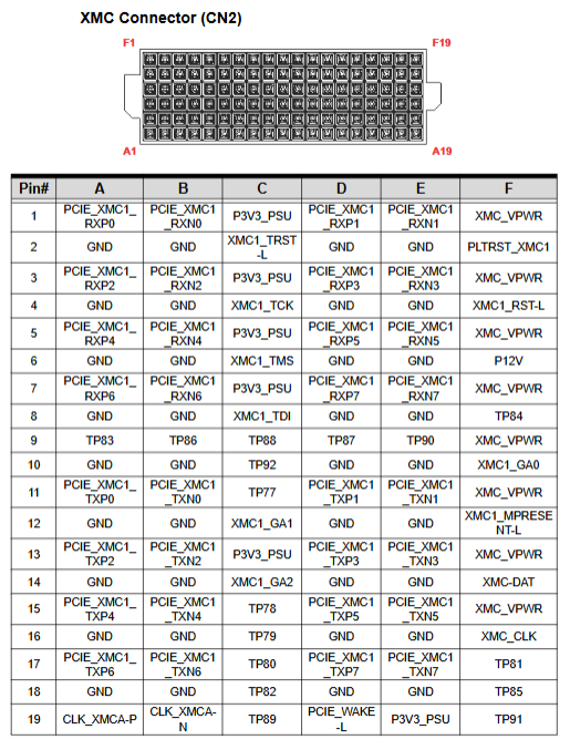
The complete manual provides gigabit network, RJ45 serial port USB3.0、DP、SATA、CFast、PMC/XMC、 Complete set of cPCI J1~J5 backplane pin signal table, distinguishing power supply, differential data, clock, interrupt, GPIO, IPMB management bus.
Hardware installation process
Step by step installation guide, including mandatory anti-static requirements:
1. CPU heat dissipation: The heat sink is pre installed at the factory and cannot be disassembled by oneself;
2 CF cards: Flip the card and remove the bracket for installation;
3 2.5-inch SATA SSD: DB-LSATA adapter board+fixed bracket;
4 CFast cards: mutually exclusive with SATA, replacing SATA daughter cards;
5 PMC/XMC sandwich card: Remove the front panel stopper, align it with the connector and lock it in place;
All installations require an anti-static workbench and anti-static wristbands, and hot swapping of storage and expansion cards is prohibited.
Driver Installation
The drive medium is ADLINK compatible All in One CD, and the installation sequence is standardized:
1. Install the operating system first;
2 chipset drivers → NET framework → graphics card → network card → SATA RST → USB 3.0 → TPM → HD audio → AMT management engine;
Provide a download channel for VxWorks BSP board level support packages.
System tool: Watchdog WDT
1. The hardware relies on the W83627UHG SuperIO chip and is controlled by LPC bus registers;
2. Function: Software feeding dog timeout, machine hard reset, prevent program jamming;
3 parameters: adjustable from 1 second to 15300 seconds timeout, supports second/minute mode, and comes with a status indicator light;
4. Provide complete C sample source code under DOS, register read and write operations, and can integrate user industrial control programs.
AMI Aptio BIOS complete setup
Press Del to enter the settings when starting up, and there are 7 main menus:
1 Main: System time, BIOS version, hardware information;
2 Advanced (Core Configuration)
PCI subsystem, ACPI sleep, TPM trusted computing, CPU (turbo/hyper threading/virtualization switch), SATA hard disk mode (IDE/AHCI/RAID), Intel TXT, AMT remote management, USB global configuration, SuperIO serial port, hardware temperature and voltage monitoring, serial port remote console (no display debugging), CPU power consumption EIST setting;
3 Chipset: BCH South Bridge PCIe、 DVMT graphics card memory allocation and memory remapping;
4 Boot: Start device priority, CSM compatibility mode, PXE network boot;
5 Security: Administrator/user startup password;
6 Save&Exit: Save/discard modifications, load optimal/fault default values;
Equipped with F2/F3/F4/F8 shortcut keys to quickly load preset configurations, serial port redirection supports remote debugging of BIOS on VT100 terminals.
POST self-test code and buzzer error
Complete AMIBIOS segmented diagnostic code:
SEC power on initialization phase (0x01~0x0B);
2 PEI memory initialization (0x10-0x4F), memory/CPU error code;
3 DXE peripheral initialization (0x60~0xCF), PCI/USB/hard disk fault codes;
4 BDS startup device detection;
5 S3 sleep wake-up and firmware recovery fault codes;
Corresponding to faults such as no memory, startup failure, password error, etc., it is used to quickly locate hardware faults during startup.