Honeywell DC1000 series PID temperature controller
Product Overview
1. Product Positioning
DC1000 is a general-purpose digital PID temperature controller based on a microprocessor from Honeywell, which has high cost-effectiveness, complete functions, and strong reliability. It is divided into four panel DIN size models:
– DC1010:1/16 DIN(48×48mm)
– DC1020:1/8 DIN(48×96mm)
– DC103:3/16 DIN(72×72mm)
– DC1040:1/4 DIN(96×96mm)
2. Typical application scenarios
Drying equipment, semiconductor packaging/testing, plastic processing, packaging machinery, spray coating, constant temperature and humidity test chamber.
3. Overview of Core Competencies
In addition to the basic switch/PID temperature control, it integrates advanced functions such as cold and hot dual PID, phase angle thyristor voltage regulation, non slip line valve position motor control, segmented program temperature rise, multi-channel alarm, automatic setting, remote setting, serial communication, etc.
Core functional features
#1. Parameter graded encryption management
Two level parameter configuration permissions, combined with a 4-digit password lock, can hide key parameters to prevent accidental modifications and unauthorized operations.
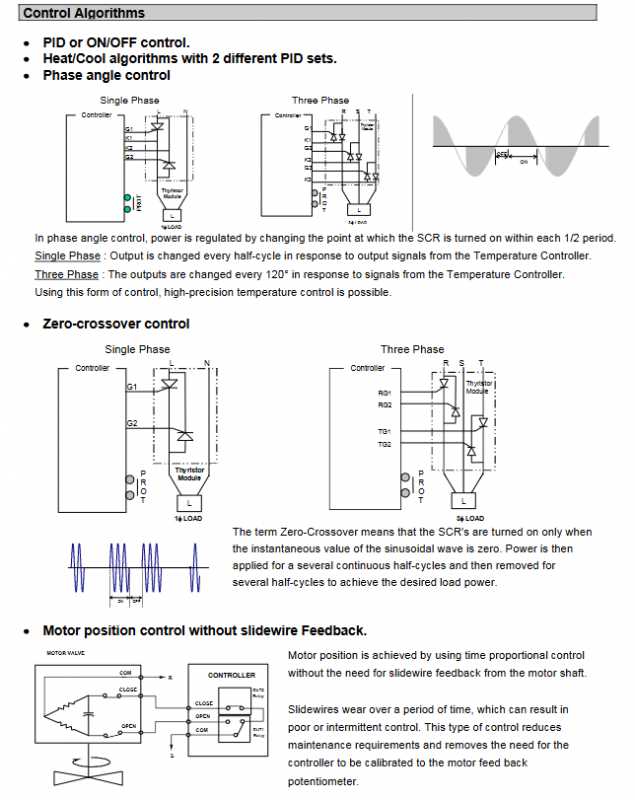
#2. Rich control algorithms (core control capabilities)
1.Basic control : ON/OFF two position, standard single path PID;
2.Dual PID for heating and cooling: Two independent sets of PID parameters for heating and cooling, suitable for integrated temperature control equipment for heating and cooling;
3. Controllable silicon phase angle adjustment(single-phase/three-phase): adjust the conduction angle every half wave/120 °, high-precision power adjustment;
4. Zero crossing conduction regulation (single-phase/three-phase): Trigger SCR only at voltage zero point to reduce electromagnetic interference;
5.Non slip feedback electric valve control: relying on time proportional control of actuator switches, eliminating the need for worn slip line potentiometers, reducing maintenance, and eliminating the need for calibration.
#3. Human computer interface (DC1030/DC1040 high-end)
-Dual 4-digit digital tube: real-time measurement value PV on the upper screen, set value SP on the lower screen;
-10 segments of LED light column display output percentage;
-Multi state indicator lights: OUT1/OUT2 output, automatic setting AT, three-way alarm AL1/AL2/AL3, manual MAN, program running PRO flashing indicator.
#4. Segmented program temperature control
Built in 2 independent programs, each with up to 8 segments; Two sets can be combined in series to form 16 complete temperature ranges, supporting automatic operation of heating, insulation, and cooling timing.
#5. alarm system
A single controller supports 3 independent alarm outputs, with 17 configurable alarm modes built-in, including timed alarm function.
#6. Auto tuning
One click self-tuning of PID parameters, quickly matching different heating/cooling loads, simplifying debugging.
#7. Remote setting function
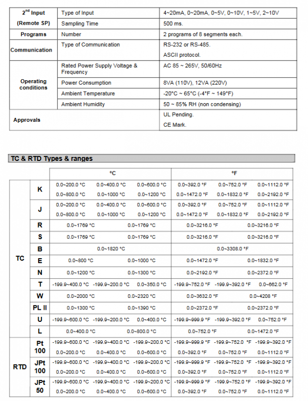
The second analog input (4~20mA/0~5V, etc.) is connected to an external signal, and the temperature setting value SP is remotely set with a sampling period of 500ms.
#8. Manual/automatic undisturbed switching
It can be freely switched between automatic PID control and manual output mode.
#9. Serial communication (optional)
Supports RS232/RS485 ASCII protocol, with a maximum of 30 DC1000s mounted on a single host; The upper computer can read PV measured values, output status, modify set values, and remotely modify all device parameters.
#10. Wide specification power supply and wide operating conditions
1. Universal power supply: 85-265V AC 50/60Hz;
2. Working environment temperature: -20 ℃~+65 ℃;
3. Working humidity of 50%~85% RH, no condensation;
4. Non volatile E2PROM is used for data storage, and power-off parameters are not lost.
Hardware input/output specifications
#1. Main measurement input (PV)
Supports all types of thermocouples TC, platinum resistance RTDs, linear analog signals (4~20mA), with a measurement accuracy of 0.5% FS at full scale; the sampling period can be set to 0~150 seconds (default 0s for 4~20mA, 1s for SSR solid-state output, 10s for relay output).
####Support temperature measuring components and ranges
1. Thermocouple TC * *: K, J, R, S, B, E, N, T, W, PL II, covering the low temperature to 1820 ℃ high temperature range;
2. * * Platinum resistance RTD * *: Pt100, JPt100, JPt50, supports low-temperature measurement from minus zero to 199.9 ℃;
3. Linear simulation: 4-20mA standard industrial signal.
#2. Second auxiliary input (remote SP)
Signal types: 4~20mA, 0~20mA, 0~5V, 1~5V, 2~10V.
#3. Output type (multiple options available)
1. Relay contact output (electromechanical type);
2. Analog output: 0~20mA/4~20mA/0~5V/0~10V/1~5V/2~10V;
3. Electric valve motor drive output (open-loop valve control);
### 4. alarm output
Independent 3-channel alarm, supporting 17 types of logic, including timed alarm.
Program and Communication Parameters
1. Program capacity: 2 sets x 8 segments, can splice 16 segments;
2. Communication interface: RS232/RS485, ASCII protocol, adjustable baud rate;
3. Power consumption: 8VA at 110V, 12VA at 220V.
Supplementary Principles of Control Algorithms
1. * * Phase angle control * *: By changing the SCR conduction time during the AC half cycle, the output power can be continuously adjusted with extremely high temperature control accuracy; Divided into single-phase and three-phase (adjustable every 120 °);
2. * * Zero crossing control * *: Trigger the thyristor only at the zero point of the AC voltage to reduce harmonic interference, suitable for equipment with high requirements for electromagnetic environment;
3. * * Non slip line valve control * *: By controlling the proportional positioning of the output duration of opening and closing the valve, there is no need to feedback the potentiometer, avoiding potentiometer wear and poor contact faults.
Body size and panel openings
The panel dimensions and installation hole specifications of the 4 models are defined separately:
1. DC1010:48×48mm(1/16 DIN)
2. DC1020:48×96mm(1/8 DIN)
3. DC1030:72×72mm(3/16 DIN)
4. DC1040:96×96mm(1/4 DIN)
Unified specifications for overall thickness and panel embedding depth.
Human computer operation buttons
1. SET key: Switch parameters, press and hold for 5 seconds to enter the first level PID setting; Left arrow+press and hold SET for 5 seconds to enter advanced secondary parameters (input, alarm, communication, calibration, etc.);
2. A/M: automatic/manual mode switching;
3. Up, down, left, and right directional keys: modify numbers, switch options;
Equipped with PV/SP dual digital tubes, light columns, and multi-channel status indicator lights.
Model selection rules
Model code segmentation selection, with 4 major dimensions:
1. Size (1/2/3/4 corresponds to four DIN specifications);
2. Main input type: TC thermocouple/RTD platinum resistance/linear signal/none;
3. Output type (relay/various analog voltage and current/motor valve control);
4. Optional options: Second input, auxiliary alarm output, RS485 communication, program functions, panel language (English/Spanish/French/Italian/German).