ADLINK MXE-200/200i Fanless Embedded Machine
Chapter 1 Product Overview (Complete Hardware Specifications)
Core computing platform
Using Intel Bay Trail Atom on-chip SoC, with 2GB DDR3L 1066 memory soldered on board (non expandable):
MXE-201: Atom E3845 quad core processor
MXE-202: Atom E3826 Dual Core Processor
Physical parameters of the whole machine
Size: 120 (W) × 100 (D) × 55 (H) mm, weight 650g
Shell: All aluminum alloy integrated heat dissipation fins, fanless passive heat dissipation
Installation method: either DIN rail buckle or wall bracket as standard
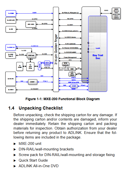
Whole machine I/O interface (distinguished by front panel and side panel)
(1) Front panel I/O
Front panel interface diagram
Buttons: Power self-locking button (press and hold for 5 seconds to force shutdown), hardware reset button
4 indicator lights: power blue light, WDT watchdog yellow light, hard drive orange light, standby blue light
Display: 1 HDMI video output, supports VGA/DVI adapter conversion
Network: Dual Intel I210IT Gigabit Ethernet ports, supporting IEEE1588 precise clock, PXE remote boot, link aggregation, WOL remote wake-up; Yellow light link, green/orange distinguishing 10/100/1000M speed
USB: 1 x USB 3.0 Type-A (blue), 2 x USB 2.0 Type-A
Storage: SD card slot (maximum 16GB SD/SDHC)
(2) Right panel I/O
Side panel interface diagram
2-channel DB9 serial port: COM1 fixed RS232; COM2 switches RS232/422/485 through BIOS
DC power supply: 3-pin plug-in wide voltage terminal, input 6-36VDC, recommended 40W power supply
Optional DB9 isolated DI/O: 4-channel isolated digital input, 4-channel isolated digital output, 1.5KV isolated withstand voltage, supports interrupt triggering
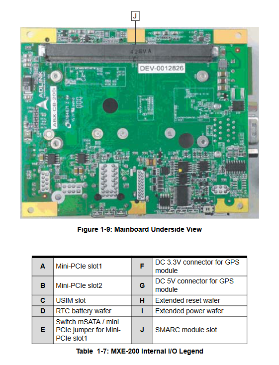
Internal expansion (motherboard mezzanine slot)
Front layout of motherboard
Dual Mini PCIe slots:
Slot1: Jumpable switch between mSATA solid-state drive/Mini PCIe wireless/4G module
Slot2: Fixed Mini PCIe, paired with a USIM socket for 3G/LTE communication
Auxiliary power supply pin: 5V/3.3V each with 1A output, exclusively for GPS module use
External pins: external power button, reset switch, status LED
RTC backup battery, SDIO controller
Industrial characteristic functions
Hardware watchdog WDT: Software programmable for 1-255 seconds/minute, hard reset of the entire machine after timeout, compatible with Windows C/C++API development library
Isolation DI/O: Industrial digital data acquisition and output, compatible with relays and sensors
SEMA cloud management tool: Linghua self-developed remote operation and maintenance, real-time monitoring of CPU/temperature/voltage/power consumption, system running time, custom flash storage
Wide temperature operation:
Standard configuration (mechanical hard drive): 0~50 ℃
Industrial mSATA solid-state expansion temperature: MXE-201-20~60 ℃/MXE-202-20~70 ℃
Storage temperature: -40~85 ℃
Reliability index:
Vibration: 5Grms three-axis 5-500Hz (with solid-state configuration)
Impact: 50G half sine 11ms (with solid state)
ESD: Contact ± 4KV, Air ± 8KV
Power consumption index
Power off standby: 0.3W
Desktop idle: 6.3W
CPU full load: 12.5W
Full I/O peak load: 22W
Packing standard
MXE-200 host, DIN rail/wall bracket, fixing screws, quick guide, all-in-one drive DVD
Chapter 2 Introduction to Installation (Hardware Disassembly and Assembly Operations)
Mini PCIe/mSATA installation steps
Remove the 8 fixing screws around the chassis and remove the bottom heat dissipation cover plate
Slant insertion mSATA/wireless 4G Mini PCIe module, press down buckle, M2.5 screw locking and fixing
Switch Slot1 function (solid-state or communication card) through motherboard jumper
Power supply wiring specifications
The side panel DC terminal V+is connected to the positive pole, V – is connected to the negative pole, and the middle is the chassis ground; Reverse connection is strictly prohibited, otherwise the whole machine will be burned.
Rail/wall mounted installation
The matching bracket locks the bottom of the chassis and is directly fixed with DIN35 rails or wall screws.
Hard requirements for heat dissipation
The heat source of the whole machine is concentrated on the left fin, with a ventilation gap of ≥ 5cm reserved at the top. It is prohibited to install it in a closed and windless manner
.
Chapter 3: Windows Driver Installation Sequence (must be executed sequentially)
The accompanying DVD comes with a complete set of drivers, and administrator privileges are required throughout the installation process. After each step, the system needs to be restarted
Chipset driver (Bay Trail underlying bus, SATA/USB controller)
Onboard integrated graphics card driver
Intel I210 dual network card driver (supporting VLAN and jumbo frames)
USB 3.0 controller driver
Universal I/O serial port/DI/O driver
SEMA operation and maintenance tool+WDT watchdog driver (essential for industrial control development)
Appendix A: Watchdog WDT and DI/O Development API
A1 Watchdog Library (Windows C/C++)
Provide header file matrix_wdt. h and library files, core API:
InitWDT: Initialize watchdog (must be called first)
SetWDT: Set timeout (1-255, unit seconds/minute optional)
StartWDT: Start timing
ResetWDT: Feed the dog, reset the countdown
StopWDT: Turn off the watchdog
If the dog is not fed after timeout, the entire machine will automatically restart hardware, which is suitable for unmanned industrial control and anti freeze.
A2 isolated DI/O digital database
Header file matrix_dio. h, core interface:
GPIOInitialize: Initialize digital channel resources
GPI-Read: Read 4 DI input levels
GPOWrites: Control the high and low levels of 4 DO outputs
GPO-Read: Read the current output status
Appendix B: Complete Aptio AMI BIOS Setup Manual
Press Del to enter BIOS during startup, with five main menus: Main, Advanced, Security, Boot, Save&Exit. Complete configuration options:
B1 Main (Basic Information)
System time, memory, CPU hardware information
System Health panel: real-time temperature, fan, overall power consumption, runtime, power on strategy
Power Up Mode: Power Off Recovery (Auto Power On/Keep Off/Last State)
ECO low-power mode, power on watchdog reset
B2 Advanced (Core Advanced Configuration, Key Industrial Control Debugging)
CPU configuration: virtualization VT, XD anti overflow protection, CPU C-State energy-saving, digital temperature sensor DTS
SATA configuration: AHCI/IDE mode, solid-state hot swappable switch
USB global settings: DOS compatible with Legacy, XHCI/EHCI takeover, independent switch for each port
SDIO memory card mode (DMA/PIO automatic)
Network Protocol Stack (PXE Network Boot Switch)
Serial LPSS configuration: COM2 RS232/422/485 mode switching
ACPI power sleep, temperature control threshold (critical point for high temperature frequency reduction/shutdown)
TX Intel Trusted Firmware Security Configuration
System Operating System Selection (Windows 7 Adaptation)
B3 Security
Administrator/user two-level boot password, restricting BIOS modification permissions.
B4 Boot startup settings
Adjust USB/solid-state/network boot priority, fast boot, boot NumLock, CSM compatibility mode (old system adaptation).
B5 Exit
Save/discard modifications, load factory stable defaults, load user-defined configurations, EFI Shell startup.
Safety operation standards
Before disassembly, completely turn off the power, perform anti-static operations, and prohibit bare contact with motherboard chips;
2 DC voltage strictly between 6-36V, overvoltage/reverse connection permanently damages equipment;
3. The chassis cannot block the heat dissipation fins, and the air duct must be ensured in high temperature environments;
4 RTC lithium batteries cannot be mixed in different models, as misuse poses a risk of explosion;
Only authorized engineers from Linghua are authorized to dismantle and repair the machine, and unauthorized dismantling will result in loss of warranty.