ADLINK NuPRO-E340 PICMG 1.3 Industrial SHB motherboard
Chapter 1 Introduction Product Overview and Core Specifications
1. Core platform architecture
CPU: LGA1155 second-generation Core 32nm processor (i7-2600/i5-2400/i3-2120/G850 Pentium), up to 3.4GHz, integrated HD core display, dual channel memory controller, DMI bus connected to PCH.
Chipset: Intel Q67 PCH (compared to the H61 of A40, supports AMT remote management, TP hardware encryption, full PCIe expansion, and multi disk RAID).
Memory: Dual channel DDR3 1066/1333, dual DIMM slots, maximum 8GB (A40 maximum 16GB), only supports 1/2/4GB non ECC memory, dual channels require the same capacity of memory.
Version: Full length PICMG1.3, size 338 × 126mm; working temperature 0~60 ℃, storage -20~80 ℃, CE/FCC A-level industrial certification.
2. Hardware feature highlights (distinguishing NuPRO-A40 core differences)
High speed storage: 2 onboard SATA 6Gbps+2 onboard+2 backplane SATA 3Gbps, a total of 6 SATA channels, supporting Intel RST, RAID0/1/5/10 arrays (A4 only has 4 SATA channels, A3 does not have 6Gbps and does not support RAID).
USB high-speed interface: rear 2 x USB 3.0 (5Gbps)+8 onboard USB 2.0+4 backplane USB 2.0, totaling 14 USB ports; USB 3.0 is only available after the system loads the driver, and DOS/BIOS does not recognize it (A4 does not have USB 3.0).
Expansion bus (PICMG1.3 core advantage): PCIe x16 independent graphics card slot is introduced from the backplane PCIe x4、 Multiple PCIe x1, 32-bit PCI buses; A4 is an old PICMG1.0 without native PCIe x16.
Network: Dual Gigabit Ethernet ports, LAN1 using Intel 82579LM, native support for Intel AMT7.0 out of band remote management, both network cards support PCIe, WOL, and jumbo frames; A4 dual network without AMT.
Security hardware: onboard Infineon SLB9635 TPM1.2 encryption chip, supporting disk encryption, VPN authentication, and secure boot (A4 without TPM).
Serial port: 6-way COM, COM1 supports RS232/422/485/485+four modes (A4 only three modes), and other 5-way standard RS232.
Supporting options: DB-Audio2 daughter card for HD audio; The onboard watchdog can be programmed at a rate of 1-255 seconds per minute, with a hard reset of the entire machine upon timeout.
3. Complete list of I/O resources
Interface type configuration details
Display rear VGA DB15; Onboard DVI-D pin (optional external baffle cable)
Rear dual RJ45 gigabit Ethernet port (LAN1 with AMT)
USB rear 2 x USB 3.0; 8-way onboard USB 2.0 pins; 4-way backplane USB 2.0
SATA 2 x SATA6G (blue seat), 2 x SATA3G onboard, 2 x SATA3G backplane
COM COM1 (2.54mm multi-mode), COM2 (2.54mm), COM3~6 (2.0mm spacing)
Peripheral pin PS/2 keyboard and mouse, 26 pin parallel LPT, HD Audio daughter card interface
Expansion (Backplane Gold Finger) PCIe x16, PCIe x4, Multiple PCIe x1, 32-bit PCI
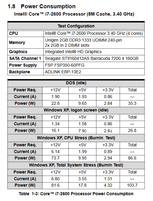
4. Power consumption (i7-2600 test)
DOS idle total power consumption 35.3W; Windows XP idle 26.8W
CPU single baking full load 86.6W; whole machine full load 103.7W
5. Factory accessories
Motherboard, 2 SATA lock data cables, USB dock cable, 2 different spacing COM dock cables, driver DVD, paper manual; The requirements for electrostatic protection are consistent with A4.
Chapter 2 Hardware Information: Hardware Connectors and Jumpers
1. Rear panel IO
There are only 4 interfaces at the back: LAN1 (AMT network) LAN2、VGA、 Dual USB 3.0; Detailed definition of USB 3.0 9-pin, RJ45 Ethernet 8-pin, VGA 15 pin pin signal and indicator light rules.
2. All onboard connectors (with layout diagram attached)
Power supply: CN24 4Pin ATX12V, must be connected to ensure CPU power supply;
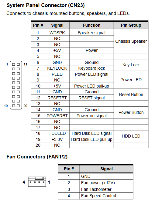
Fan: FAN1 (CPU fan), FAN2 system fan, 4Pin supports speed detection+PWM speed regulation;
Storage: CN2/4 (SATA6G blue), CN5/7 (SATA3G black) 7-pin standard SATA pins;
Display: CN17 DVI-D 20 pin plug, optional external DB24 board cable for matching;
Serial port: distinguish between 2.54mm (COM1/2) and 2.0mm (COM3-6) spacing, COM1 supports four mode switching;
Peripherals: 26 pin parallel port, 20 pin front panel (power on/reset/hard disk light/beep/keyboard lock), CN27 PS/2 keyboard and mouse 6-pin pin, CN9 HD Audio daughter card interface;
Backplane expansion gold fingers: PCIe x16/x4/x1, PCI, SATA, USB exit channels.
3. Function jumper
JBAT1 Clear CMOS: Power off and short circuit 2-3 to clear BIOS and system time;
COM1 mode JP1-4 four sets of jumpers: RS232/422/485/485+four levels are achieved through multiple jumper combinations (A4 only has two sets of jumpers, lacking 485+); No independent watchdog to disable jumper, WDT is controlled by BIOS switch.
Chapter 3 Getting Started Hardware Installation Process
General electrostatic specifications
Power off throughout the entire process, anti-static wristband/workbench, do not touch LGA1155 slot contacts, damage will result in loss of warranty.
1. LGA1155 CPU installation
The steps are exactly the same as NuPRO-A40: release the lock rod → lift the pressure plate → remove the protective cover → align the CPU triangle mark with slot Pin1 → lay the CPU flat → fasten the pressure plate and lock rod, and violent pressing is strictly prohibited.
2. Installation of radiator
Apply thermal grease evenly to the CPU and connect the fan to FAN1; The maximum ambient temperature inside the chassis is limited to 50 ℃, and not installing heat dissipation will permanently damage the CPU and motherboard.
3. DDR3 memory installation
Dual DIMM slots, notch alignment buckle, dual channels must have two identical capacities; Supports 1/2/4GB of memory, with a maximum of 8GB. It is recommended to use the same brand and CL delay model.
Chapter 4 Driver Installation Complete Driver Installation Guide
system support
Windows XP/7 32/64 bit Fedora14、RHEL5; USB 3.0 cannot be used for XP system installation (without native drivers), Linux kernel ≥ 2.6.31 can be installed using USB 3.0.
Driver installation sequence (DVD corresponding directory)
Intel RST Fast Storage Driver (XP installation requires F6 floppy disk loading, RAID/AHCI enabled)
Q67 chipset INF driver
. Net Framework 3.5 (Kernel Display Pre Dependency)
Intel HD integrated graphics card driver
Dual Gigabit Network Card Driver
RST Management Tool (Disk Array Visualization)
Intel AMT Remote Management Driver
TPM security chip driver
USB 3.0 controller driver
DB-Audio2 audio sub card driver (BIOS first enables Azalia audio)
Follow the prompts to restart the system after each installation step.
Chapter 5 BIOS Setup AMI Aptio UEFI Complete Configuration
Press Del to enter BIOS when starting up, press F7 to quickly start the menu, F10 to save and exit, ESC to abandon modifications; Compared to the A40 BIOS, it has added TPM, AMT, USB 3.0, PCIe multi port, and TXT security exclusive menu.
5.1 Main Page
Display BIOS version, overall memory, system time/date, administrator privileges, and basic time modification function.
5.2 Advanced Settings (Added Unique Module)
ACPI settings: sleep S1/S3, AT/ATX power mode, sleep switch;
Trusted Computing: TPM chip enabled/disabled, key cleared, operating mode (exclusive to E3, not available in A4);
CPU configuration: number of cores, VT virtualization, XD protection, turbo frequency/energy-saving strategy;
SATA configuration: IDE/AHCI/RAID three mode, hard disk interleaving, hot plug;
Intel TXT security technology: Hardware trusted execution environment, relying on TPM+VT activation;
IGD graphics card configuration: DVMT memory allocation, dual display output settings;
USB configuration: Added USB 3.0 switch, XHCI/EHCI handover settings, and independent switches for all ports;
Super IO serial parallel port: 6-way COM independent switch, address IRQ configuration;
Hardware Monitor hardware monitoring: intelligent temperature controlled fan (automatic/full speed/manual three modes), real-time CPU/mainboard temperature, and various voltages;
AMT configuration (core features): external remote management switch, BIOS/OS dual watchdog timing;
Serial console redirection: COM0-6 remote terminal parameters (baud rate, flow control, terminal type), supporting Windows EMS out of band management.
5.3 Chipset Chipset Settings
Graphics card memory bridge: VT-d pass through, main display device, core graphics memory, multi screen switch;
PCH bridging: 82574LAN network card switch, power-off recovery logic, HD audio switch, PCIe 0-3 port mode (single x4 or four-way x1);
ME management engine subsystem: AMT firmware switch, boot prompt, MEBx management interface.
5.4 Boot Start Menu
Start sequence NumLock、 Silent Logo, CSM compatibility mode, PCIe network card ROM switch, distinguish UEFI/traditional Legacy boot.
5.5 Security Menu
Two level password (administrator/boot user), forgotten password needs to be reset by clearing CMOS; TPM comes with security verification.
5.6 Exit Exit menu
General functions such as saving/discarding restarts, factory recovery, and single temporary device startup.
Appendix A: Watchdog WDT
Function: 1-255 seconds/minute software timer, timeout system hard reset, register mark WDT to trigger restart;
Development materials: The manual provides complete example code for the underlying C operation of IT8783 SuperIO, and the DVD comes with a complete project that can achieve WDT activation, timing configuration, dog feeding, and GPIO linkage output.
Appendix B: System Bottom Hardware Resources (Industrial Control Development)
Complete memory mapping, DMA channels, IO port addresses, PIC/APIC dual-mode IRQ interrupts, PCI bus topology, PCI interrupt routing table; Compared to A40, new entries for USB 3.0, AMT, TPM, and multi PCIe device resource allocation have been added.