ADLINK M-302 ATX Industrial Motherboard
Chapter 1 Product Overview (Specifications, Architecture, Hardware Configuration)
Packaging Standard List
M-302 motherboard, I/O backplane, 2 SATA data cables, 2 SATA power cables, 4 serial port backplane cables, driver CD, paper user manual; Upon receipt, the integrity of the accessories must be verified, and any damage must not be powered on.
Core hardware specifications
(1) Processor support
LGA775 slot, FSB 533/800/1066MHz, Compatible with the full range of 775 industrial CPUs:
Core 2 Duo (E7400/E6400/E4300), Pentium Dual Core (E5300/E2160), Pentium 4 (651/551/531), Celeron/Celeron D; E7400 requires BIOS version A1.2 or above.
(2) Memory
Four 240pin DDR2 DIMM dual channel slots, supporting 533/667/800MHz unbuffered memory with a maximum of 8GB; 32-bit XP system recognition memory will be less than 4GB and does not support 128 bit granular, double-sided x16 memory.
(3) Chipset and Display
Beiqiao Intel Q965 GMCH (integrated with GMA3000 graphics card, sharing a maximum of 256MB of video memory, up to 2048 × 2048) 1536@75Hz VGA output); Nanqiao ICH8DO; Equipped with PCIe x16 dedicated graphics card slot for external graphics card connection.
(4) Storage system
6-way SATA II 300MB/s interface (ICH8 native), 1-way PCIe extension Ultra ATA 133 IDE; Support mechanical hard drives SSD。
(5) Expansion slot
1 x PCIe x16, 1 x PCIe x4, 5 x standard PCI, with sufficient expansion capability, suitable for sports cards, acquisition cards, and communication cards.
(6) Onboard I/O interface
Network: Intel 82566DM Gigabit RJ45 Ethernet port, supporting WOL remote wake-up and link indicator lights;
Serial port: 2 rear DB9 COM, onboard pins COM3/COM4, a total of 4 RS232 channels;
USB: Rear 4 USB 2.0 ports, onboard 3 sets of pins for expanding 6 USB ports, totaling 10 ports;
Other: parallel port, PS/2 keyboard and mouse, 6-pin IEEE1394a, HD audio (Line in/Line out/Mic in), floppy drive interface;
Optional: TPM security encryption module (onboard dedicated slot).
(7) Exclusive industrial control functions
Programmable watchdog WDT: Timing unit can be selected in seconds/minutes, with a range of 1-255. It will automatically reset the entire machine’s hardware upon timeout, and comes with the underlying C read-write source code;
Hardware monitoring W83627DHG: Real time collection of CPU/motherboard temperature, three-way fan speed,+3.3/+5/+12 voltage, high/low voltage alarms;
Power on and power-off memory: power-off recovery can choose to turn on/keep off/restore the state before power-off;
Remote wake-up: network card WOL, modem ringing power on, timed RTC power on, USB keyboard power on.
(8) Environment and Electrical
Working temperature: 0-60 ℃, storage: -20~80 ℃, humidity: 10%~90%, no condensation;
Certified CE/FCC A-class industrial standards;
Provide actual power consumption data tables for two CPUs, Pentium 4 651 and Core 2 E6400, under DOS/XP idle/full load multiple operating conditions.
Hardware architecture diagram
The CPU is connected to Q965 Northbridge via 533/800/1066MHz FSB, which controls dual channel DDR2, integrated VGA, PCIe x16 dedicated graphics slots; North Bridge DMI 2GB/s link connects to ICH8DO South Bridge; Nanqiao unified control includes 6 x SATA, 10 x USB, PCI bus, PCIe x4, HD sound card, Super I/O (serial/parallel/fan monitoring), 1394, TPM slot SPI BIOS。
Board layout and mechanical dimensions
The standard ATX size is 304.80 × 243.84mm; the drawing fully indicates the CPU slot, 4 memory slots, all expansion slots, fan sockets, SATA/IDE/COM/USB/audio/TPM/CMOS clear jumper, and front panel pin positions.
Chapter 2: Complete Definition of Connectors and Jumpers
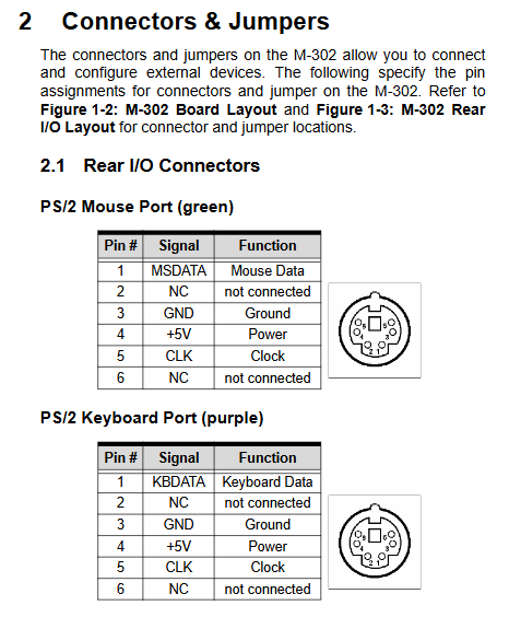
2.1 Rear I/O panel interfaces (PS2, VGA, parallel port, etc.) USB、 Ethernet port, 1394, audio)
Provide complete pin signal definitions for DB9, DB15, DB25, RJ45, 6-pin 1394, and 3.5 audio sockets one by one, including network port tri color speed indicator logic (10M orange flash/100M orange constant light/1000M green light).
2.2 Onboard built-in pins (bottom/side of motherboard)
Covering all internal cable interfaces, including pin function table:
Power supply: 24 pin main ATX, 4 pin ATX12V auxiliary power supply;
Fans: CPU fan (4-pin speed regulation), 2 sets of system fans (3-pin speed regulation), power fan;
Storage: 6-way SATA, 40pin IDE, 34pin floppy drive;
Communication: COM1-4 serial ports, IR infrared, 1394 pins, LAN status light pins;
Peripherals: 6-way extended USB, front audio AAFP, SPDIF digital audio;
Chassis: Front panel pins of F_PANEL (power button, reset, power light, hard disk light, buzzer);
Security: TPM encryption module dedicated slot.
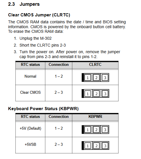
2.3 Key jumpers (only 2 sets)
CLRTC (clear CMOS): 1-2 short circuit=normal; After power failure, short circuit 2-3 to clear BIOS parameters, and use for fault repair;
KBPWR (keyboard power supply): 1-2=standby+5V; 2-3=standby 5VSB, suitable for remote keyboard startup.
Chapter 3 Hardware Installation Operation Guide
3.1 LGA775 CPU Installation Specification
Power off and anti-static operation; Open the buckle, lift the protective cover, align the golden triangle of the CPU with the bottom left corner of the slot, place it vertically and horizontally, and prohibit violent pressing; After installation, a cooling fan must be installed to prevent overheating, system crashes, and motherboard damage.
3.2 DDR2 Memory Installation
Dual channel rule: A1/A2 is channel A, B1/B2 is channel A; it is recommended to have consistent memory capacity and CAS latency for the same channel; Slot gap anti misoperation design, with automatic locking of the two side buckles when inserted.
3.3 Driver installation sequence (primarily Windows XP)
Intel 965 chipset INF driver (basic support for underlying bus, SATA, USB);
GMA3000 integrated graphics card driver;
Intel Gigabit Network Card Driver;
Realtek/ADI HD audio driver;
After each installation step is completed, the system must be restarted; The driver is stored in the designated directory on the accompanying CD, and updates can be downloaded from the official website.
Chapter 4 Phoenix Ward BIOS Full Menu Detailed Explanation
Press Del to enter the settings when starting up. There are 12 main menus with shortcut keys for operation (F5 restore, F6 secure default, F7 optimize default, F10 save exit):
Standard CMOS Features: System time, IDE/SATA hard drive recognition, startup error shutdown strategy, total memory display;
Advanced BIOS Features: CPU temperature control, C1E energy-saving, XD antivirus, hyper threading, boot device priority, serial remote console, boot password security option;
Advanced Chipset Features: 15M-16M ISA holes reserved for memory, integrated/discrete switching, DVMT memory allocation, PCIe port switch;
Integrated peripherals: SATA mode (IDE/AHCI/RAID), serial/parallel address mode, USB switch, onboard network card/audio enable, power on/off strategy;
Power Management Setup: ACPI S1/S3 sleep mode, PCI/network card/serial port remote wake-up, timed power on, hard disk sleep mode, forced shutdown by long pressing the power button for 4 seconds;
PnP/PCI configurations: IRQ resource automatic/manual allocation, PCI latency, multi monitor priority;
PC Health Status: Real time reading of voltage, temperature, fan speed, high temperature alarm threshold;
Frequency/Voltage Control: Spread spectrum EMI suppression;
9-13: Load fault safety default, factory optimization default, administrator/user two-level password, save exit, exit without saving.
Chapter 5 POST Power On Self Test Code
Complete hexadecimal POST code comparison table, covering the entire process of CMOS detection, memory recognition, CPU initialization, bus enumeration, peripheral detection, BIOS loading, system boot fault location, and core reference for maintenance and troubleshooting.
Two core appendices
Appendix A Development of Watchdog Timer (WDT)
Based on the W83627DHG super I/O chip, we provide complete C language operation source code under DOS: unlock SIO, select logical devices, enable WDT, set timeout unit (seconds/minutes), configure countdown, feed dog reset complete set of register operation code, adapted to unmanned industrial control program anti crash.
Appendix B: Complete Resource Mapping of the System
Memory address mapping (BIOS, APIC, ISA hole, video buffer);
DMA channel allocation;
Fixed/Variable I/O Port Address Table;
PIC/APIC two modes IRQ interrupt allocation;
PCI bus device configuration space, PCI interrupt routing summary table;
Used for resolving IRQ and I/O address conflicts in multi card industrial control systems.