ADLINK PCI-8132 Two Axis Servo/Stepper Motion Control Card
Chapter 1 Product Overview (Hardware Core Specifications and Functions)
1. Core hardware performance parameters
Bus and pulse
32-bit PCI2.2 33MHz, PnP dip free address/IRQ;
Pulse output up to 2.4Mpps, two output modes: OUT/DIR (pulse+direction), CW/CCW (positive and negative dual pulse);
Encoder feedback: EA/EB/EZ differential signal, supports 1/2/4 harmonics, up to 2.4MHz input, 28 bit bidirectional counting (range -134217728~+134217727).
Motion curve
Support trapezoidal acceleration and deceleration, smooth S-shaped acceleration and deceleration; Support two axis linear interpolation, continuous constant speed motion, and dynamic speed regulation during motion.
Isolation IO system (all 2500Vrms optoelectronic isolation)
Each axis dedicated motion IO: positive and negative limit PEL/MEL, deceleration limit PSD/MSD, origin ORG, encoder Z-phase EZ; servo dedicated INP in place, ALM alarm, ERC deviation reset, SVON servo enable, RD driver ready;
Universal IO: 16 isolated digital outputs, 16 isolated digital inputs;
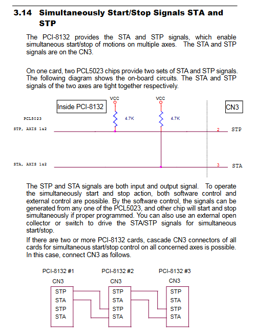
Extended signal: Handwheel PA/PB differential input, hardware position triggered CMP1/CMP2, multi card synchronous STA/STP start stop.
Hardware features and functions
FPGA hardware location comparison: supports single/multi-point touch table (up to 1024 points), outputs 100us trigger pulse, suitable for visual photography and flying cutting;
Multi card cascade synchronization: CN3 interface cascades multiple cards to achieve synchronous start/stop of all axes;
3 types of return to zero modes, handwheel following operation, multi class interrupt triggering, and complete matching interface for servo drive.
Electrical and Environmental
Onboard power supply: PCI+5V; External independent 24V power supply for isolated IO, onboard DC-DC generates external 5V;
Working temperature: 0-50 ℃; Half length PCB size;
The whole machine can work in parallel with up to 12 cards without address conflicts.
2. Supporting software system
Motion Creator: a Windows visual debugging tool (only available on Win95/98/NT) that allows for debugging of axis parameters, motion curves, and IO status without the need for programming;
Bottom level function libraries: DOS Borland C, Windows C/C++, VB DLL, hundreds of motion/IO/interrupt APIs, supporting real-time industrial control systems.
Chapter 2 Hardware Installation, Jumper and Interface Definition
1. Packing list
PCI-8132 motherboard, 100 core SCSI cable, 24V power supply terminal wire, user manual, driver CD.
2. Hardware installation specifications
Anti static operation, only insert into the 32-bit white PCI slot, not into the ISA slot;
PCI is plug and play, and BIOS automatically assigns base addresses and IRQs without the need for dialing;
Troubleshooting: Black screen/device conflict during startup, enter BIOS to adjust PCI interrupt allocation.
3. Three major connector functions
CN1: External 24V power terminal
Connect external DC24V to the isolated IO circuit, and the onboard DC-DC output 5V external power supply must be connected to 24V, otherwise the IO cannot work.
CN2: 100 core SCSI main interface (all motion, encoder, universal IO)
Divided into two sets of axis signals (axis 0/axis 1), 16DI, 16DO, handwheel PA/PB, CMP trigger, external 5V/24V power output, the manual provides a complete pin definition table.
CN3: Synchronous start stop terminal
STA synchronization starts, ST synchronization stops, and multi card CN3 is cascaded with each other to achieve global synchronous motion; Comes with PCI 5V pull-up.
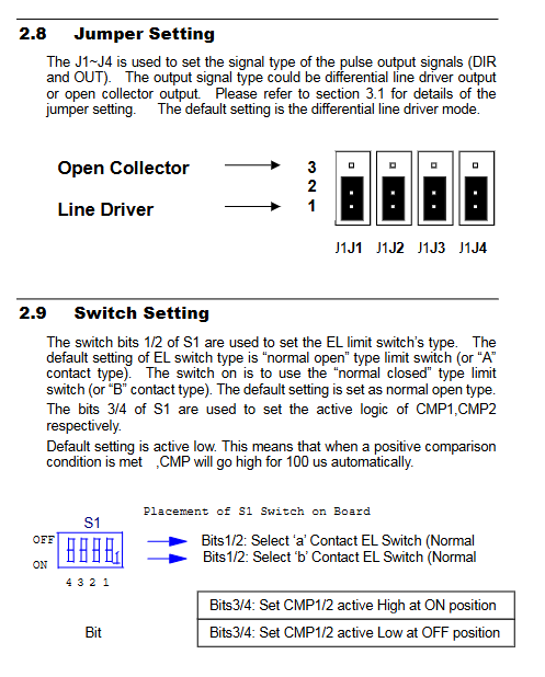
4. Onboard dialing code S1
Bit1/2: Limit switch normally open/normally closed selection (default normally open A contact);
Bit3/4: CMP1/CMP2 triggers polarity (default low valid, matched with 100us high pulse output).
Chapter 3: Instructions for All Signal Wiring
Explain the electrical characteristics and differential/collector wiring schemes of each signal category by category, including circuit diagrams:
Pulse output OUT/DIR
Differential drive output (default), compatible with collector mode; Maximum current of 20mA; switch between two pulse logic software.
Encoder EA/EB/EZ
Differential input, compatible with external collector encoders (requires series current limiting resistors: 5V without resistance, 12V series 1.8k, 24V series 4.3k); Supports 4x counting.
Limit/Origin (PEL/MEL/PSD/MSD/ORG)
24V input, built-in filtering and stabilization; The SD deceleration signal triggers automatic deceleration to the starting speed, and the EL hard limit immediately stops pulse output.
Servo specific signal
INP: Servo in place signal, can be software enabled to wait for in place before determining the completion of the motion;
ALM: Driver alarm triggers immediate deceleration/emergency stop, resulting in interruption;
ERC: Deviation reset, automatically output 100ms pulse when returning to zero/limit/alarm/emergency stop, clear servo deviation counter;
SVON: Servo enabled open collector electrode output; RDY driver ready input.
Universal DI/DO
DI supports 5~24V input; DO is TD62083 Darlington output, with a withstand voltage of 50V and a maximum single channel of 500mA; all optical isolation is 2500V.
Handwheel PA/PB, CMP trigger, multi card synchronous STA/STP
CMP point matching output standard 100us pulse, suitable for camera triggering; Multi card cascade wiring diagram provided.
Chapter 4 Working Principle of Motion Control (Core Motion Algorithm)
1. Seven major sports operation modes
Constant speed motion
Trapezoidal and S-type acceleration. During operation, call _8132_v_change to modify the maximum speed in real time, and support dynamic speed regulation.
Point motion (trapezoidal curve)
Absolute coordinate a_move, relative coordinate r_move; Support symmetric/asymmetric acceleration and deceleration; When the travel is insufficient, it automatically switches to a triangular curve without shaking.
S-curve point motion
Segmented S acceleration and deceleration (S acceleration section+linear acceleration section), reducing mechanical impact and extending equipment life; The parameter includes the duration of S acceleration/deceleration.
Two axis linear interpolation
X/Y synchronous start stop, allocate speed of each axis according to distance, support composite vector speed, used for planar straight line machining.
Zero Return to Origin (3 Modes)
Mode 0: Stop at ORG origin only;
Mode 1: Trigger ORG and quickly search for EZ index before stopping;
Mode 2: ORG triggers deceleration, searching for EZ index at low speed (high-precision zeroing);
Can latch ORG signal to prevent short pulse loss.
Hand wheel manual mode
PA/PB reading handwheel pulse, 1/2/4 harmonics optional, limiting maximum following speed; Support single wheel control for dual axis.
Multi card synchronous motion
CN3 cascade+_8132umove_all function, all axes start and arrive simultaneously.
2. Servo IO, limit, encoder logic
INP/ALM logic programmable, capable of setting alarms for immediate shutdown or deceleration shutdown;
SD deceleration signal, EL hard limit software enable/disable, customizable high and low level effectiveness;
Encoder counting source switching: internal instruction pulse/external grating feedback, used for fully closed-loop platforms.
3. Hardware location comparison (visual/flying cut core)
Support custom comparison criteria (greater than/equal to/less than the count value);
Support 1024 point array tables and linear interval point generation functions;
Output hardware pulses and optional interrupts during matching, without the need for real-time polling by the upper computer.
4. Interrupt system
13 types of configurable interrupt sources: limit trigger, zero return completion, point in place, encoder error, CMP matching, abnormal handwheel, etc; DOS provides interrupt service programs, while Windows handles interrupts through thread events.
Chapter 5: Motion Creator Visual Debugging Software
Only supports Windows 95/98/NT, resolution ≥ 800 × 600, divided into three major operating interfaces:
Main interface: Identify all PCI-8132 cards, display card numbers IRQ、 Base address, quickly select axis;
Axis configuration window: one-stop configuration of pulse mode, encoder multiplier, limit polarity, zero return mode, interrupt source, servo IO logic, configuration can save 8132.cfg file for program loading;
Axis operation interface
Real time display of instruction position, actual encoder position, and position error;
Visualize the selection of trapezoidal/S-curve, absolute/relative/continuous/handwheel/zero return modes;
Real time monitoring of all DI/DO, limit, servo IO red and green status indicator lights;
Can set repetitive reciprocating motion, one key start stop, emergency stop;
The software can directly verify wiring, motion curves, and triggering functions for pre project debugging.
Chapter 6: Bottom level Function Library (Development Core)
Complete C/C++and VB function prototypes, divided into 19 major categories of APIs, with accompanying syntax, parameters, return values, and example code:
Initialization class: board scanning, opening/releasing, loading configuration files;
Pulse/Encoder Configuration: Pulse Mode, Encoder Doubling, Counting Source Switching;
Constant speed, trapezoidal, and S-shaped motion functions;
Two axis interpolation and multi card synchronous motion;
Return to zero, manual control of handwheel;
Movement status reading (whether in place, limit triggering, alarm);
Servo IO and limit logic configuration;
Universal DI/DO read and write;
Position comparison table, trigger output;
Interrupt configuration and event handling.
All function threads are thread safe, providing two complete sets of example code for DOS interrupt ISR and Windows event threads.