ETEL TMB+series standard torque motor
Overall architecture of product series
1. Two product lines with large body outer diameters
TMB+0140 series (outer diameter 140mm)
Core thickness models: 030, 050, 070, 100, 150, 200; Winding code RA/SA/SB/UB;
TMB+0175 series (outer diameter 175mm, larger torque range)
Core thickness models: 030, 050, 070, 100; Winding code RA/RB/TB/VB;
2. Winding coding selection logic (distinguishing speed and torque characteristics under the same body/core)
The mechanical dimensions of the same motor are completely identical, only the windings are different, covering a wide speed range:
RA/RB: high torque, low base speed, maximum sustained torque, suitable for low-speed heavy-duty indexing;
SA/TA: Medium torque, medium speed balanced type;
SB/TB: Low to medium torque, higher rated speed;
UB/VB: Minimum torque constant, maximum no-load limit speed, suitable for high-speed rotating platforms;
Rule: The later the winding code, the smaller the Kt torque constant, the larger the rated current, the higher the maximum speed, and the continuous torque slightly decreases.
The four core parameter modules of the data table
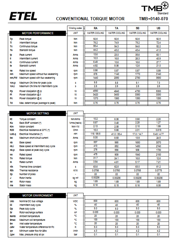
Module 1: Motor performance (torque, current, speed, losses, cogging torque)
Torque index
Tp peak torque, Ti intermittent torque, Tc continuous torque, Ts static torque; The greater the thickness of the iron core, the synchronous increase of four torques;
Td cogging torque (average peak value): slightly increases with the increase of iron core thickness, affecting low-speed stability;
Current indicator (Arms effective value)
Ip peak current, Ii intermittent current, Ic continuous current, Is static current; The rated current of the high-speed winding (UB/VB) is significantly higher;
Speed index
NS rated low speed;
Maximum rotational speed before weak magnetic field at nm (base speed); Nm, the maximum speed limit of FW after activating weak magnetic field;
Nb base speed, nb, i intermittent working condition base speed, nb, p peak working condition base speed, nn rated speed;
Heat loss
Pp peak loss, Pi intermittent loss, Pc continuous loss, water cooling takes away heat;
Power on duration: maximum peak power on time for ron and p, maximum intermittent power on time for ron and i, to prevent coil overheating.
Module 2: Electrical characteristics of motors (key to servo drive matching)
Kt torque constant (Nm/Arms): The more turns a winding has, the greater the Kt, and the greater the torque output for the same current;
Ku back electromotive force constant (Vrms/(rad/s)): linearly positively correlated with Kt, determining bus voltage matching;
Km motor quality factor (Nm/√ W): characterizes the torque heating efficiency, and the higher the value, the smaller the heating;
R20 20 ℃ phase resistance, Ld/Lq orthogonal axis inductance: affecting current loop response and heating;
Isc short-circuit current: Design basis for winding short-circuit protection;
Unified pole count of 2p=22 poles, with no change in the number of magnetic poles across the entire series;
Module 3: Mechanical Inertia and Mass
J rotor moment of inertia: The thicker the iron core, the heavier the rotor, and the inertia J synchronously increases, affecting the dynamic response;
MR rotor quality, MS stator quality: selection basis for overall weight of the machine;
Module 4: Water cooling environment parameters (forced water cooling, air-cooled models)
Electrical environment: nominal bus Udc=600VDC;
Load condition: Di=40% intermittent duty cycle, Dp=5% peak duty cycle;
Temperature limit: The environment is 20 ℃, and the maximum allowable temperature for the coil is 130 ℃;
Water cooling requirements:
Inlet water temperature 20 ℃; Continuous full load water temperature rise Δ θ w=5K;
Minimum cooling water flow rate (L/min): The thicker the iron core, the greater the required flow rate;
Maximum pressure drop of Δ pw waterway (bar);
The heat transfer area of the Sr rotor increases linearly with the thickness of the iron core;
Explanation of torque speed characteristic curve
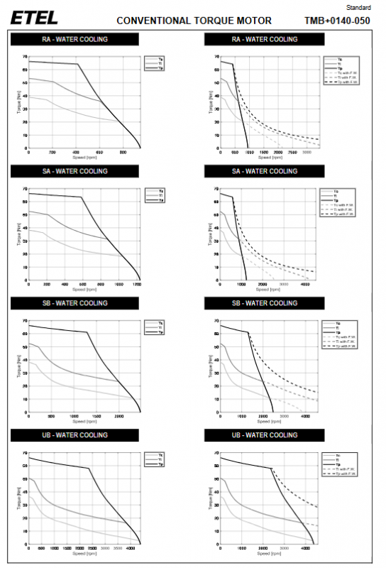
Each winding provides two types of characteristic diagrams:
Solid line graph (without weak magnetic nm range)
Three solid lines: Tc continuous torque, Ti intermittent torque, Tp peak torque; Horizontal axis speed rpm, vertical axis torque Nm; low-speed torque is flat, and after reaching the base speed, the torque drops linearly;
Virtual real mixed image (including weak magnetic nm, FW extended range)
Solid line: No weak magnetic torque curve; Dashed line Tc FW/Ti FW/Tp FW: the upper limit of high-speed torque after activating weak magnetic field. Weak magnetic field can significantly widen the maximum speed, but the output torque decreases significantly at the same speed;
Curve pattern:
Iron core thickness increase: overall torque in the full speed range shifts upward, with a slight decrease in base speed;
Winding switching to UB/VB: The base speed and weak magnetic limit speed are significantly increased, but the torque in each gear decreases synchronously;
Comparison of core differentiation among various sub series
1. TMB+0140 (140 outer diameter)
Core 030 → 200, continuous torque 21.6Nm~156Nm; The maximum speed of UB winding with weak magnetism can reach 4590rpm; Suitable for small and medium-sized indexing tables, optical turntables, and detection equipment.
2. TMB+0175 (175 outer diameter, larger load)
Core 030 → 100, continuous torque 33Nm~132Nm; The rotor has a higher inertia and carries a larger load, which is commonly used for the fourth axis of machine tools and heavy-duty precision rotating fixtures.
Core Applications and Design Points
Mandatory requirement for heat dissipation: The entire system is only water-cooled for heat dissipation, and must meet the minimum flow rate and inlet water temperature, otherwise the coil will be damaged due to overheating;
Driver matching logic
Selecting RA/RB winding for low-speed heavy load: reducing the requirement for rated driving current;
Selecting UB/VB winding for high-speed rotating platform: sacrificing torque for high speed;
Load cycle design
The peak operating condition only allows a 5% duty cycle and has a maximum single power on time limit, and cannot output at full peak for a long time; The 40% duty cycle of intermittent working conditions is the long-term standard working range;
Mechanical selection and selection
Thickening the iron core increases torque, but increases rotor inertia, resulting in slower dynamic start stop response; High speed dynamic equipment prioritizes thin iron cores and high-speed windings; Heavy duty indexing equipment uses thick iron core low-speed windings;
Safety Tips
Motor overspeed will generate a reverse electromotive force far exceeding 600V, and the driving side must be equipped with overvoltage relief and speed limit protection.