ADLINK USB-7230/USB-7250 Isolated Digital I/O Module
Product core positioning and differentiation between two major models
1. Overall commonality
High speed USB 2.0 bus, powered by USB bus (5V/400mA), no external power supply required
Full channel 2500VRMS optoelectronic isolation, eliminating ground loops and high-voltage breakdown prevention
Standard detachable 40Pin screw terminal for easy wiring
Multi functional base: desktop installation, DIN rail installation, wall mounted for three purposes
Built in 2 independent 32-bit frequency/event counters, supporting up to 1MHz input
Software functions: digital filtering, input state change detection (COS), programmable power on output state
Comes with a free U-Test upper computer, allowing for testing of all IO functions without the need for programming
2. Model hardware differences
Parameter USB-7230 USB-7250
Digital input 16 common terminal optoelectronic isolation DI 8 differential bidirectional optoelectronic isolation DI (non-polar)
Digital output 16 drain MOS isolated DO 8 electromechanical relays (4 C-type+4 A-type)
Load driven single channel maximum 250mA, supports 5-35V external load contact maximum 2A, AC/DC universal (250VAC/220V DC)
3. Typical application scenarios
Automotive parts testing, laboratory signal acquisition, industrial automation IO control, multi-channel signal switching, production line point monitoring
Complete hardware specifications and parameters
(1) General Physical/Electrical Environment
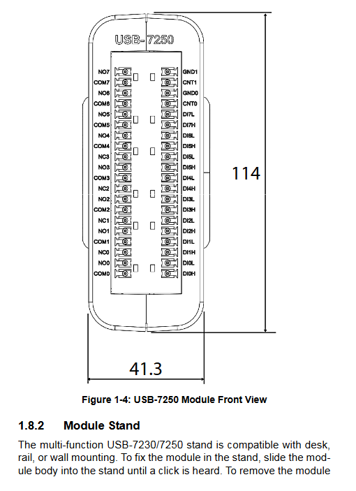
Size: 156.5 (L) × 114 (W) × 41.3 (H) mm
Interface: Mini USB high-speed 2.0, two sets of 20 pin detachable screw terminals (totaling 40 pins)
Working temperature and humidity: 0~55 ℃, humidity 10%~90%, no condensation
Storage temperature and humidity: -20~70 ℃, humidity 5%~95%, no condensation
(2) Isolated digital input DI (two general electrical standards)
Isolation voltage withstand: Channel to ground 2500VRMS
Level: High level 5~24V, low level 0~1.5V, supports dry contacts
Input internal resistance of 2.4k Ω; supports software programmable digital filtering (minimum pulse width starting from 20.83ns)
COS detection: recognizes level jumps, can capture a minimum of 20.83ns pulse, software delay beyond 1kHz will result in event loss
USB7230: Single common COM port; USB7250: Differential DI (DI-H/DI_L, regardless of polarity) for each channel
(3) Frequency/Event Counter (two identical)
Channel: 2 independent optoelectronic isolation counting channels CNT0/CNT1
Count register: 32-bit, configurable rising/falling edge trigger count
Input frequency range: 0.1Hz~1MHz (DC coupling)
Measurement error: ≤ 50kHz with an error of 0.5%; 50k~500kHz with an error of 1%; 500k~1MHz error 2%
(4) USB-7230 MOS isolated output DO
16 channels of open drain MOS transistor isolated output
Load power supply range: 5~35VDC, single channel continuous current up to 250mA
Inductive loads (relays/coils) must be externally connected with current diodes to protect MOS transistors
Power on, USB disconnect can customize DO initial level
(5) USB-7250 relay output
8-way mechanical relay: the first 4 Form C (normally open NO+normally closed NC+common COM), the last 4 Form A (only normally open NO+COM)
Contact specifications: maximum switching power 60W/125VA; Maximum voltage 250VAC/220V DC; Maximum current 2A
Action time 2ms, release time 1ms, maximum contact resistance 75m Ω
Lifespan: 1 million actions under 50V/0.1A resistive load
Power on/off USB default relay disconnection, supports software customization of power on status
Mechanical structure and three installation methods
The whole machine is equipped with a multifunctional base as standard, and three installation modes can be quickly switched. A complete set of dimensional engineering drawings are attached:
Desktop flat placement: The base directly supports the device without the need for additional accessories
DIN rail installation: Paired with rail kit, the buckle is fixed to the standard industrial DIN rail for easy disassembly and assembly
Wall mounted installation: The base is reserved with 4 Φ 3.4 screw holes, with hole spacing of 13mm horizontally and 20.4mm vertically, fixed with flat head screws
List of Structural Accessories (Factory Standard)
Host, multifunctional base, two sets of detachable 40pin terminals, 2-meter locking USB cable, rail installation kit, driver CD, paper manual
40Pin terminal pin definition
1. USB-7230 terminal signal
DI0~DI15:16 isolated inputs, shared COM common terminal
CNT0/CNT1: Two counting inputs, CGND counting ground
DO0~DO15: 16 MOS isolated outputs, IGND output returns to ground
VDD: External load power input (DO circuit power supply)
2. USB-7250 terminal signal
DI0H/L~DI7H/L: 8-channel differential bidirectional isolated input
CNT0/CNT1, GND0/GND1: Two counting channels
COM0~COM7: Relay common terminal
NO0~NO7: normally open contacts (0~3 with NC normally closed contacts)
Hardware operation and functional principles
1. Optoelectronic isolation input circuit
Adopting PC3H4 optocoupler isolation and high-low bidirectional diode protection to prevent reverse connection damage; USB7230 common input, USB7250 differential non-polar input, compatible with any 24V sensor and dry contact.
2. COS state transition detection
Real time monitoring of level changes in all DI channel hardware, generating interrupts to report to the USB controller after jumping; After the register is read, it automatically resets to zero, suitable for point-to-point alarm and trigger scenarios.
3. Programmable digital filtering
48MHz reference clock, filtering range 1~65535, corresponding to a minimum pulse width of 20.83ns~1.365ms; Filter electromagnetic interference spikes on site, and provide waveform examples before and after filtering in the attached document.
4. Frequency/Event Counting Principle
Hardware captures edges and converts frequencies based on the reference clock cycle; Supports two modes: simple counting (total pulse count) and frequency measurement, with error curve charts attached.
5. Key points of USB7230 MOS output
Inductive loads must be connected in parallel with a freewheeling diode between VDD and IGND; The software can read back the current output status and automatically turn off all DO when the USB is unplugged.
6. USB7250 relay logic
Form C: Output 1 COM to NO, output 0 COM to NC
Form A: Output 1 COM connected to NO, output 0 disconnected
All relay status software can read, default disconnection when powered on, supports custom initial state
Software drivers and supporting tools
1. Bottom layer driver library
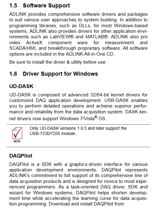
UD-DASK: 32/64 bit kernel driver, version 1.0.5 and above support this module, provides DLL development library, adapts to C/C++custom industrial control programs
DAQPilot: A graphical task-based SDK with built-in wizards to lower programming barriers and support calling LabVIEW, MATLAB, and SCADA configuration software
2. Free upper level tool U-Test
No need to write code, can achieve: DI real-time monitoring, DO manual control, counter reading, simple FFT signal analysis, built-in on the factory CD, downloadable and updated on the official website
3. System support
Full range Windows (Vista/Win7 32/64 bit), driver CD comes with a complete chipset and IO driver installation package
Quick power on installation process
Start up the computer and install the complete set of drivers from the All in One CD first
Connect the standard locking USB cable to the USB 2.0 port of the computer
Device power on initialization: The indicator light is amber to load firmware, and it turns green after completion
Device ID setting: Rotate the dial at the rear of the device (0-7), multiple modules of the same model must have different IDs set to avoid conflicts
Dismantling/Wiring: After power failure, remove the detachable screw terminal and connect the sensor and relay load
Attention to power supply
The module relies entirely on USB 5V/400mA power supply; If the power supply to the computer’s USB port is insufficient and the device cannot be recognized by the system, the rear motherboard USB port needs to be replaced.
Safety operation standards
Before installing, disconnecting, or replacing accessories, the USB power supply must be disconnected
Prohibit equipment from coming into contact with liquids or high-temperature sealed environments, maintain ventilation and heat dissipation, and avoid touching and scalding the equipment surface at high temperatures
The input and output voltage strictly follow the specifications, and it is prohibited to connect high-voltage isolation and withstand voltage exceeding 2500V to prevent module breakdown and burning
The fault can only be repaired by authorized Linghua engineers, and dismantling the machine by oneself will result in loss of warranty; Avoid squeezing and damaging the power cord
There is a risk of explosion due to incorrect replacement models of built-in backup lithium batteries. Waste batteries should be recycled and disposed of in accordance with environmental regulations
It is recommended to deploy the equipment in the computer room or restricted operation area to prevent unrelated personnel from accidentally wiring and causing electric shock