ADLINK MNET-4XMO/MNET-4XMO-C distributed 4-axis motion control module
Basic Information
Product model differentiation
MNET-4XMO: Standard 4-axis Motionnet distributed pulse motion module with basic motion control functions;
MNET-4XMO-C: Enhanced version, adding three visual specific functions: high-speed position comparison trigger, continuous path motion, and fast indexing, adapted to AOI linear array camera synchronous acquisition;
Core bus: Based on NPM Motionnet high-speed serial distributed motion bus, master-slave architecture, multi module cascade expansion axis number;
Applicable scenarios: automation equipment, point processing, multi axis linkage, AOI optical inspection, and synchronous line scanning imaging of coil materials.
MNET-4XMO hardware real shooting
Core hardware specifications of the entire machine
1. Core hardware parameters for sports
Controllable number of axes: single module 4-axis independent servo/stepper control;
Maximum frequency of pulse output: 9.9MHz, differential OUT/DIR pulse signal;
Encoder feedback: EA/EB/EZ differential signal per axis, maximum 20MHz input in 4x mode;
Position counter: 4 sets of 32-bit counters per axis (instruction position, mechanical actual position, deviation counter, universal counter);
Hardware comparator: 5 channels per axis for 32-bit position comparison;
Acceleration and deceleration curves: programmable T-trapezoid, S-curve, Bell curve, to suppress start stop vibration;
Interpolation ability: arbitrary 2-axis arc interpolation, 2-4 axis straight line interpolation;
Zeroing mode: Built in 13 automatic origin search+multiple sets of complete zeroing logic (ORG/EZ/EL limit combination).
2. Motionnet bus communication parameters
Communication speed dialing options: 2.5/5/10/20Mbps (default 20Mbps);
Single bus maximum node: 64 MNET slave modules, with a maximum of 256 total control axes for a single bus;
Cable specifications: CAT5/CAT5e/CAT6 twisted pair, multiple drop handle cascading;
20Mbps with 64 modules: total length ≤ 50m; 20Mbps with 32 modules: total length ≤ 100m; 10Mbps with 64 modules: total length ≤ 100m;
Communication fault protection dialing: When the network is disconnected, you can choose to “stop the machine urgently” or “keep the current motion”;
Interface: Dual RJ45 HS1/HS2, supports cascading the next slave station.
3. Power supply and machinery
Module power supply: 24VDC ± 10%, maximum 0.3A;
IO peripheral power supply: independent 24V IO power supply, supporting common ground/isolated ground jumper switching;
Dimensions: 165.3 (L) × 74.9 (W) × 52.7 (H) mm;
Working temperature range: 0 ℃~70 ℃, storage -20 ℃~80 ℃.
4. Overview of onboard connectors and dip/jumper cables
Dial code from station ID
Communication speed dialing
EMG enable jumper
CM1~CM4 (4-channel servo DB interface): Single axis complete set of servo signals
Differential pulse OUT ±, direction DIR ±; encoder EA/EB/EZ ±; SVON servo enable, ALM servo alarm, INP in place, RDY driver ready, ERC deviation reset, EM emergency stop output, brake brake brake differential signal.
IOIF1~IOIF4 (mechanical limit IO terminal)
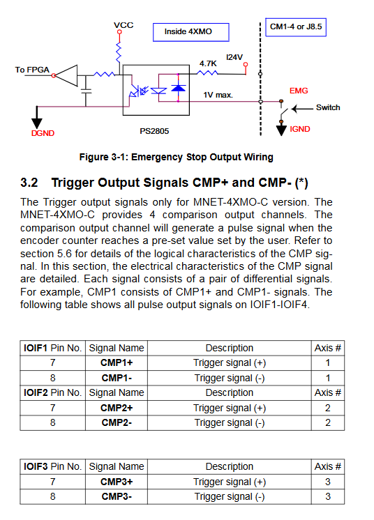
PEL positive limit, MEL negative limit, ORG origin, universal DI/DO for each axis; 4XMO-C additionally adds CMP ± differential trigger output;
CN1: 4-axis independent differential brake signal;
J8 terminal: 24V power supply for the whole machine, EMG emergency stop input, ground FGND, IO common terminal DICOM;
Dial switch function:
S1: Set the slave station ID (0~63) for 6-digit dialing;
S2: Switch Motionnet communication rate with a 2-digit dip code;
S3/S5: Is the DO output used for servo alarm reset;
S6: Bus terminal resistance TMR, communication fault TUD logic;
S7: Servo signal ground FGND common ground/isolation;
Jumper JP:
JP4: Enable/disable global EMG emergency stop signal;
JP5/JP6: Modules 24V and IO24V share power supply or are isolated power supply.
5. Digital IO resources
Universal DI: 1 channel per axis, a total of 4 channels (4 additional channels for 4XMO-C, totaling 8 channels), 24V optocoupler isolation, source/drain software switching;
Universal DO: 1 channel per axis, a total of 4 channels (4 additional channels for 4XMO-C, totaling 8 channels), open collector, maximum 35V/50mA drive;
Special limit IO: Positive and negative hard limit of PAL/MEL, ORG origin sensor input;
Emergency stop EMG: Global hardware emergency stop input, triggered to lock all pulse outputs.
6. MNET-4XMO-C exclusive visual trigger hardware (not available in the standard version)
CMP differential position comparison trigger output: 4-axis independent differential trigger;
Two triggering modes:
Table mode: 8192 points per axis, with a total of 32768 points per axis;
Linear high-speed mode: Single axis triggered up to 1MHz, pulse width adjustable from 0.1 μ s to 1s;
Path continuous path motion: Pre stored at least 2048 trajectory segments, automatic reloading, constant speed continuous motion, significantly reducing host CPU usage;
Fast Index function: high-speed segmented positioning, suitable for continuous shooting of roll line scanning.
Motionnet master-slave system architecture
Motionnet master-slave topology
Main controller selection (3 types of hosts)
DPAC-3000: Distributed PAC, integrated Motionnet+HSL dual bus;
PCI-7856: PCI bus motion+IO main card;
DB-8153: MNET main module compatible with PCI-8154/8158;
Topology: Hand in hand multi node cascade, half duplex NRZ differential communication, real-time issuance of motion instructions with cyclic cycles;
Communication mechanism: The host sends data packets, which are parsed and executed by ASIC hardware. All onboard hardware operations such as motion interpolation and counting take up almost no PC CPU;
Signal transmission: Single cycle sending and receiving of 4-byte instructions, supports interrupt asynchronous data transmission, real-time microsecond level.
Specification for Signal Wiring Circuit
The manual provides a complete schematic diagram of all signal optocouplers/differential drivers, and the key points of core signal wiring are as follows:
Pulse OUT/DIR: 26LS31 differential output, maximum external driving current ≤ 20mA;
Encoder EA/EB/EZ differential input: common mode voltage ± 7V, external wiring drives the encoder;
Limit/ORG/DI input: PS2805 optocoupler isolation, supports NPN drain/PNP source sensors, software switching logic normally open/normally closed (NL/NH);
SVON/ERC/DO output: open collector, up to 35V withstand voltage, drives servo enable, alarm reset, solenoid valve;
CMP trigger (4XMO-C): differential 26LS31 output, directly connected to the image acquisition card trigger input;
EMG emergency stop: It is recommended to use a normally closed switch. Once triggered, immediately stop all pulse outputs and reset the software to restore it.
Principles of core functions of motion control
1. Single axis motion mode
Speed mode: Continuous constant speed output, real-time override to modify speed during operation, supports T/S acceleration and deceleration;
Point motion: relative/absolute positioning, automatically adapting to shorten the maximum speed according to the length of the journey (eliminating the impact of triangular trajectories);
Real time online modification: covering the speed and target position during the motion process, and changing parameters without stopping the axis.
Trapezoidal/S-curve velocity curve
Point motion speed contour
2. Multi axis interpolation motion
2-4 axis linear interpolation: multi axis synchronous start stop, vector speed control, each axis moves synchronously in a fixed proportion;
2-axis arc interpolation: Set the center coordinates, rotation angle (clockwise/counterclockwise), and constant tangent velocity;
All interpolation operations are completed by onboard motion ASIC hardware, without relying on real-time calculations from the host.
Two axis linear interpolation
Arc interpolation trajectory
3. Origin Regression (Home) System
13 sets of automatic origin search logic, combining ORG origin, EZ encoder zero position, positive and negative limit EL, supporting:
First search for the limit and then reverse to find the origin;
After triggering the origin, count the specified EZ pulse and reset it to zero;
Segmented deceleration to zero and offset compensation;
Return to zero to automatically reset the deviation counter and output ERC reset servo driver.
Return to zero mode timing diagram
4. Detailed explanation of MNET-4XMO-C visual specific functions
Position comparison triggers CMP
When the encoder count reaches the preset value, it automatically outputs differential pulses, and the adaptive line array camera synchronously takes photos; Support triggering conditions greater than/equal to/less than, high and low level/flip pulse output;
Path path continuous motion
Batch pre store multiple interpolation trajectories, automatically load the next segment during motion, maintain a constant speed throughout the process without pause, and the host only issues one task, suitable for continuous inspection of coil materials;
Fast Index: Segmented and fast positioning, combined with triggering to achieve equidistant image acquisition.
Supporting software system
Driver and Function Library APS
Windows WDM driver, unified APS motion function library, compatible with Linghua’s full range of pulse motion cards; Supports C/C++, VB, and Delphi development, with APIs including axis parameters, point positions, interpolation, zeroing, position comparison, and a complete set of IO read and write interfaces.
MotionCreatorPro 2 upper level debugging tool
Windows visualization graphics software, no programming required:
Scan and identify all MNET slave stations on the bus;
Visualize the configuration of axis parameters, acceleration and deceleration, and zeroing modes;
Real time monitoring of position, speed, limit/alarm IO status;
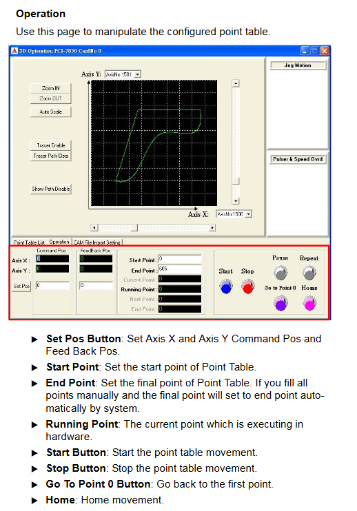
Single axis/interpolation motion simulation debugging, CMP trigger point table editing;
Fault code inquiry and communication diagnosis.
Supported systems: Windows 2000/XP/Vista.
Hardware dialing and jumper setting operation guide
The manual is divided into chapters to fully explain the ON/OFF corresponding functions of each set of switches:
S1 slave ID: 6-digit binary dialing code, 0-63 unique address, cannot be duplicated on the same bus;
S2 speed: 2-digit combination 2.5/5/10/20Mbps, it is recommended to lower the speed for longer cables;
S6 TUD fault logic: ON=network disconnection to maintain movement, OFF=network disconnection to stop the machine;
JP4 EMG jumper short circuit=global emergency stop enabled, disconnect=shield emergency stop;
JP5/JP6: Short circuit=module 24V and IO24 are grounded together, disconnect=strong and weak electrical isolation, recommended isolation in strong interference environments.
Safety, Installation, and Maintenance Standards
Static protection: When disassembling and assembling modules, it is necessary to wear a grounded anti-static wristband;
Wiring sequence: Connect IO/servo cables first, and finally connect 24V power supply; Disconnect the power before plugging in the terminals;
Grounding specification: The strong electromagnetic field servo FGND must be grounded, and the shielded network cable must be grounded at one end;
Load limit: DO output load cannot exceed 35V/50mA, pulse differential load current ≤ 20mA;
Fault handling: EMG emergency stop trigger, servo ALM alarm, and bus communication interruption all have hardware latches, which need to be cleared by software before restarting the operation;
Packaging accessories: Host, quick manual, cables, terminal board are optional.
Summary of Core Differences between Two Models
Function MNET-4XMO (Standard) MNET-4XMO-C (Visual Enhancement)
CMP position differential trigger output without 4-axis independence, up to 1MHz
Point triggered table storage without 8192 points per axis
Path continuous path motion without support for pre stored multi segment trajectory automatic operation
Fast Index does not support high-speed segmentation positioning
DI/DO quantity 4DI+4DO 8DI+8DO
Typical applications include general automation, multi axis processing AOI line scanning, and synchronous visual inspection of coil materials