ADLINK NuDAM-6100 series DIN rail installation, RS-485 bus distributed IO module
Basic Information
General hardware specifications
Communication: Two wire RS-485; Baud rate 1200-115200bps; A single segment bus can have up to 256 nodes and a maximum distance of 1200m;
Power supply:+10~+30VDC non regulated DC;
Environment: Working temperature -10 ℃~70 ℃; Storage -40~85 ℃; Humidity 5-95% without condensation;
Dual watchdog: ① Module hardware watchdog (monitoring the operation of the module itself); ② Host Watchdog: When the upper computer fails or communication is disconnected, the module automatically switches the output to the preset safe value to ensure process safety.
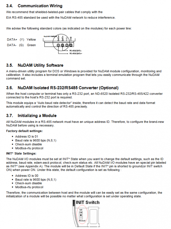
Initiat configuration switch: Module hardware dip switch, turn ON (Init) to power on and enter default mode: Address 00, baud rate 9600, no checksum. Used to modify module address, baud rate, checksum, and communication protocol; Normal work must be switched back to Normal. The new version of the firmware supports software software’s Initiat command, without the need to toggle hardware switches.
Protocol switching: By default, ASCII/Modbus RTU can be configured at the factory. After switching, the module needs to be restarted to take effect.
Module hardware list and hardware parameters
1. Module Overview
Model Channel Configuration Isolation Instructions
ND-6150 8-way isolated DI+8-way isolated open drain (P-MOSFET) DO 3750Vrms isolation, DO maximum 650mA per channel, with short-circuit protection
ND-6160 4-channel isolated DI+4-channel relay output; RL1/RL2 Form-A is normally open; RL3/RL4 Form-C conversion contact relay contact: 0.6A@125VAC / 2A@30VDC
ND-6117 8-channel analog input; 6-differential+2-channel jumper differential/single ended isolation, supporting multiple voltage and current ranges
ND-6124 4-channel analog output (voltage/current configurable)+4-channel isolated DI; 14 bit DAC; Support output slope Slew Rate 3000VDC isolation, with independent configuration of each channel range
2. Mechanical structure
Dimensions: 142.2 × 71.55 × 100.7 mm; Supports DIN rail installation;
Terminal layout: power VS/GND, DATA+, DATA-RS-485 bus, Initiat switch, IO signal terminals;
Onboard Block Diagram: Provide complete internal schematic diagrams for ND-6150, ND-6160, ND-6117, and ND-6124, respectively;
Wiring diagram: Provide complete wiring diagrams for dry contact, wet contact DI, relay load, analog differential/single ended input, and AO voltage/current output.
System installation and initialization
3.1 Composition of the entire system
NuDAM-61xx IO module;
RS-232/USB to RS-485 converter;
+10-30VDC industrial power supply;
NuDAM-6100 Utility configuration software;
Engineering requirements for RS-485 bus: shielded twisted pair, 120 Ω terminal resistance at both ends of the bus; DATA+and DATA – polarity are unified across the entire network.
3.2 New module initialization process
The module is powered off, and Initialize is set to Initialize (ON); Power on and enter default state ID=009600 N-8-1;
The PC is connected to the module through an RS-485 converter; Use tools to scan modules;
Set the unique module address, baud rate, checksum and communication protocol (ASCII/Modbus ‑ RTU);
Power off, initiate to switch back to normal;
Connect to the on-site RS-485 bus and confirm that the baud rate and verification mode of the entire network are consistent.
Firmware D02.01 and above support software Initiate: send~AATnn to set timeout,~AAI to enable software Initiate, without the need to toggle hardware switches to modify parameters.
3.3 New modules added to existing networks
Initialization must be completed on a single machine first, setting addresses and baud rates that do not conflict with the existing network; Power off before connecting to the bus to avoid address conflicts.
3.4 Module Configuration Table
The manual provides baud rate codes, input range codes, data formats, AO output type codes, and Slew Rate code tables for various models.
ND-6117 AI: Supports ± 10V, ± 5V, ± 1V, ± 500mV, ± 150mV, -20~+20mA;
ND-6124 AO output types: 0-20mA, 4-20mA, 0~+10V, ± 10V, 0~+5V, ± 5V; slew rate can be configured from instant output to maximum 2048mA/s, 1024V/s.
NuDAM-6100 Utility Configuration Software
Running on the Windows platform, used for debugging and configuring modules.
Main functions: serial port parameter configuration, full network scanning module; Terminal emulator manually sends ASCII commands; Module parameter settings (address, baud rate, protocol, watchdog, power on output value, safety output value); Firmware ISP online upgrade.
Windows 7 and above will encounter runtime error 70 (permission denied). Solution: Control Panel – User Account Control UAC to lowest, restart the computer.
Readable/modifiable: module name, firmware version, watchdog parameters, power on output value, fail safe value; Simulate module calibration.
NuDAM ASCII Command Protocol
5.1 Command Common Format
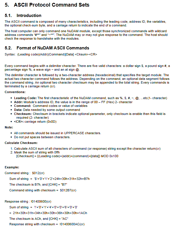
Guidebook+Two digit hexadecimal address+Command+[Data]+[Optional checksum]+<CR (0x0D)>
Address: 00-FF; Broadcast Wildcard * *;
Response:! />Representing success;? Representing failure; Some broadcast commands (# * * synchronous sampling,~* * Host OK feeding dogs) have no response;
Checksum: Sum up all ASCII characters, modulo 0x100, enabled on high noise scenes.
5.2 Command Grouping
General configuration command (all modules)
%AANNTTCCFF sets module address, type, baud rate, and data format; Modifying the baud rate/checksum requires an Initiate state;
$AA2 reading module configuration; $AAF reads firmware version; AAM reading module model; ~AAO custom module name;
AAPN switches ASCII/Modbus RTU protocol; AAP reads the current protocol;
$AARS software restart module; AAS1 factory restoration; $AA5 reads the reset flag to determine if the module has been powered off and restarted.
DIO module (ND-6150/6160) command
#**Broadcast synchronous latch DI; $AA4 reads synchronous sampling;
$AA6/@ AA reads DI/DO status;
#AAxxxx sets DO output, supports single channel writing and batch writing;
Input latch function: can capture short pulses, AALS reads latch status, AAC clears latch;
~AACPSS modifies IO polarity logic.
ND-6117 Analog Input Command
#AA reads all channels AI; # AAN reads N single channel;
Support channel switch and independent setting of each channel range;
AA0 full-scale calibration Span; AA1 zero offset calibration.
ND-6124 Analog Output Command
#AAN (data) sets AO output, supports engineering units/complement hexadecimal;
$AA9NTTSS sets channel output type and slew rate Slew Rate;
Support reading actual read back output; Set default power on output value and watchdog fault safety output;
Support emergency DI: DI triggering can force AO to enter safe output.
Watch dog complete set of instructions (industrial safety focus)
~**Host feeding dog broadcast (no return), the upper computer must periodically send it;
~AA3EVV on/off host watchdog, set timeout (unit 0.1s, range 0.1-25.5s);
~AA2 reads watchdog configuration; ~AA0 reads watchdog timeout flag; ~AA1 clears timeout flag;
~AA5V stores the power on output value/watchdog fault safety value; ~AA4V reads the power on/safety output value.
Modbus RTU protocol support
Firmware D02.01 and above supports Modbus RTU, fixed frame format: 8 data bits, no checksum, 1 stop bit.
Supports standard Modbus function codes:
01 Read coil, 02 Read discrete input, 03 Read hold register, 04 Read input register;
Write single coil in 05 and single register in 06; 15 write multiple coils, 16 write multiple registers;
70 (0x46) Manufacturer customized read-write module parameters.
Register Mapping: The manual provides a complete mapping table of all coils, discrete inputs, input registers, and hold register addresses for ND-6150/6160 (DIO), ND-6117 (AI), and ND-6124 (AO).
Data format: Analog quantities support engineering unit format, binary complement format, and the manual comes with conversion formulas and complete read-write example messages.
Exception codes: including illegal functions, illegal addresses, illegal data, and watchdog timeout exceptions.
Appendix Important Function Description
Appendix A: Initialization switch: Hardware dialing operation steps. If the module parameters are forgotten, switch to Init and power on. Use address 00 to read the configuration. The new version supports software initialization.
Appendix B module status: power on reset, hardware watchdog reset, output jumps to power on value; The host watchdog timeout output jumps to a safe value, and a timeout flag is set. The command to clear the flag is required to restore the output.
Appendix C Dual Watchdog Mechanism
Module hardware watchdog: monitors the MCU of the monitoring module itself. If it crashes, the entire machine will be reset;
Host Watchdog: monitors the upper computer/communication link, outputs a safety value when timeout occurs, and prevents device loss of control.
Appendix D Reset Status Mark: Power on/Hardware Reset Position Mark; Clear the flag after reading $AA5 for the first time, which is used by the program to determine whether the module has restarted.
Appendix E Input Latch: DI channel hardware latch pulse signal, short pulses will not be lost; Command is required to clear the latch status.
Appendix F Power on Value/Safe Value
Power on value: output when the module is powered on/hardware reset;
Security value: The host watchdog will force output after timeout, and the user will save it in advance.
Appendix G Protocol Switching Steps: Switching ASCII/Modbus RTU in Initiate mode requires a restart to take effect.
Appendix H ND-6117 AI Calibration: Operating Procedure for Zero and Full Scale Calibration.
Appendix I ND-6124 AO Calibration: Voltage and current output zero/full-scale calibration requires a standard multimeter/milliampere meter, module preheating for 30 minutes, and factory calibration parameters can be restored.