ADLINK PCIe 8560+PXI 8565 PCI Express to PXI Remote Bus Expansion Kit
Product Overview
The entire kit consists of two boards and a dedicated shielded expansion cable:
PCIe 8560: Host side card, inserted into the PCIe x1 slot of the computer;
PXI-8565: The PXI chassis side controller must be installed in the System Slot of the PXI chassis and cannot be plugged into a regular peripheral slot;
Connect the two using shielded twisted pair cables; The maximum transmission distance can reach 7 meters.
Working Principle
PCIe 8560 built-in signal equalizer; The PXI-8565 contains PCIe to PCI bridge chips internally; The PCIe x1 (2.5Gbps bidirectional) on the host side is transmitted through external cables and remotely converted into a standard 32bit/33MHz PCI bus for the entire PXI chassis.
Completely hardware transparent, no need for additional drivers; All modules inside the PXI chassis are directly plugged into the PCI slots of the local motherboard for the operating system.
Core specifications
Project PCIe 8560 (host side) PXI 8565 (PXI chassis side)
Bus standard PCIe Base Spec 1.0a PCI-to-PCI Bridge Spec1.2, supports 3.3V/5V PCI
Link PCIe x1, bidirectional 2.5Gbps output 32-bit/33MHz PCI bus
Power consumption 3.3V, maximum 210mA 3.3V, maximum 720mA
Working temperature: 0-50 ℃; Storage -20~80 ℃; Humidity 10-90%, no condensation
Cable options ACL-EXPRESS-1 (1m), ACL-EXPRESS-3 (3m, standard) ACL‑EXPRESS‑7(7m)
Key Features
PCIe x1 interface, capable of remote expansion of PXI chassis up to 7 meters away;
Transparent to the operating system and does not require additional software drivers;
Compatible with 3.3V and 5V PCI devices; 32bit/33MHz full PCI bandwidth;
Onboard signal equalizer, output swing, de emphasis jump pin, used for long-distance cable signal quality adjustment;
PXI-8565 supports Spread Spectrum Clock to reduce EMI electromagnetic radiation.
Typical Applications
Electronic manufacturing testing, high-density I/O systems, industrial automation, military aviation testing, remote testing in harsh environments, image acquisition systems.
Packing List
PCIe 8560 motherboard
PXI-8565 PXI System Slot Controller Board
ACL-EXPRESS-3 (3-meter extension cable)
User Manual
Hardware installation and power on sequence
Static sensitive devices, anti-static wristbands and anti-static workbenches throughout the process.
2.1 Installing PCIe 8560 (Host Computer)
Turn off the host and disconnect the power supply;
Insert PCIe 8560 into any PCIe x1 slot of the host and tighten the baffle screw;
Close the computer case.
2.2 Installing PXI-8565 (PXI chassis)
PXI chassis power off status;
Insert PXI-8565 into the PXI system slot System Slot (normal peripheral slots are prohibited); Tighten the upper and lower fixing screws.
2.3 Cable Connection
Connect the CN1 interface of PCIe 8560 and the CN1 interface of PXI 8565 at both ends of the cable, and tighten the fixing screws of the connectors;
It is strictly prohibited to use equipment with hot swappable cables; The system crashes and data is damaged during live plugging and unplugging; Two devices need to be restarted after accidental disconnection.
2.4 Strict power on/off timing (very critical)
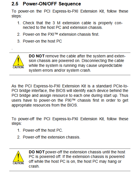
Power on sequence: First turn on the PXI remote chassis power supply → then start the host PC
During the BIOS boot self-test phase, it is necessary to identify the PXI devices behind the bridge; If the PC is turned on first, the BIOS cannot recognize the remote PXI module and resource allocation fails.
Shutdown sequence: First turn off the host PC, then turn off the PXI chassis power
If the host is still running and the PXI chassis is turned off directly, it will cause the host to crash and hang.
2.5 LED status indicator light
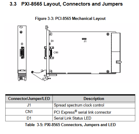
PCIe 8560 and PXI 8565 both have D1 link status LED;
LED lighting conditions: reliable cable connection+PXI chassis powered on+host entering POST power on self-test stage.
Board hardware jumper settings
PCIe 8560 (motherboard)
CN1: External cable interface; D1: Link status LED
S1, S2: Signal equalizer skipping pin, S1 sends and S2 receives, both must be set synchronously; Four levels are available: strongest, medium, weak, and off balance; The factory default is the strongest; Long distance transmission can adjust and improve signals as needed.
Pin3: Output signal swing control; Pin4: Output De Emphasis control; Factory default high level.
PXI-8565 (PXI chassis end)
CN1: External cable interface; D1 Link Status LED
J1: Spread spectrum clock control jump pin; Default enabled to reduce EMI electromagnetic interference; Can be closed.
Troubleshooting FAQ
What is the maximum extension distance?
The maximum length is 7 meters, providing three types of dedicated cables: 1/3/7 meters. The kit must be used to match the cables, and regular PCIe cables are not available.
Do you need additional drivers?
No need, it belongs to the standard PCIe PCI bridge and is natively supported by Windows.
How many expansion cases can a host carry?
One PCIe link can only connect to one remote PXI chassis; To have multiple chassis, the host requires multiple idle PCIe slots, with one PCIe 8560 inserted into each slot corresponding to a set of remote chassis. The theoretical PCI specification has a maximum of 255 segments of PCI bus, but it is limited by the PC motherboard BIOS/chipset.
What is the source of compatibility issues?
Most of the problems come from the BIOS’s inadequate allocation of multi segment PCI bus resources. Suggest using Intel 945, 965 and newer chipset motherboards.
Compatibility issue handling methods
Update the motherboard BIOS to the latest version;
Disable idle devices on the motherboard from releasing IO resources;
Replace different PCIe slots on the host;
Insert the modules into the expansion chassis one by one, and sequentially power on to locate the faulty modules.
Safety instructions
Disassembling and assembling hardware must be powered off; The equipment prohibits liquids, high temperature and high humidity; Unauthorized personnel are prohibited from disassembling and repairing; Incorrect replacement of lithium batteries poses a risk of explosion.