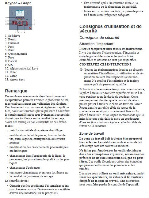
Atlas Copco Power Focus 3000 Controller
Mandatory requirement for core process (verification of tightening results)
After any event that affects the tightening process occurs, the tightening torque result must be verified. Trigger verification scenario: initial installation; Parts/bolts/tools/software/configuration/environmental changes; Electrical connection modification; Production line technology, quality process, operator replacement, etc. Verification execution timing: It must be executed after initial installation, maintenance, and repair; At least once per shift or at an appropriate frequency for the enterprise; Confirm that the joint conditions of the threaded pair have not changed.
Security Information
1. General safety regulations
Only for use in indoor industrial environments, explosive hazardous environments are prohibited; Installation and maintenance can only be carried out by qualified personnel.
When working simultaneously with welding equipment, the workpiece must be independently grounded to prevent welding reflux current from flowing through the controller grounding cable. The cross-sectional area of the grounding wire should be at least equal to that of the welding machine reflux cable.
Keep the homework area clean and bright; Unrelated personnel should stay away from the work area.
The equipment must be reliably grounded, and the removal of grounding pins and the use of adapter plugs are prohibited; Prohibit equipment from being exposed to rain and water. Keep the equipment away from electrical noise sources such as arc welding to reduce electromagnetic interference.
Do not drag or pull the power cord, and replace any damaged cables immediately; The power cord is the main disconnect device, and it must be unplugged before opening the cover for maintenance.
Personal protection: Stay focused during work; Loose clothing, jewelry, and long hair are prohibited; Prevent accidental tool startup; Maintain a stable standing posture.
Workpieces must be fixed with fixtures during processing, and handheld work is prohibited; Equipment malfunctions must be repaired before use.
2. Key points of GFI grounding fault protector
It is strictly prohibited to use an isolation power supply with an isolation transformer to power the controller, as it may cause the GFI ground fault protector to fail.
The controller backplane is equipped with a GFI test button, which must be pressed once a month for protection function testing; When the protector trips and loses power, it is necessary to first investigate the root cause of the fault before resuming production.
3. Compliance certification
CE EU compliance: meets EMC electromagnetic compatibility and low voltage directives; Compliant with EN series coordination standards.
RoHS (2011/65/EU) Hazardous Substance Restrictions; The WEEE (2012/19/EU) electronic waste directive states that products are marked with a crossed trash can, and scrapped parts cannot be used as household waste and should be collected by customer service centers.
US Canada certification: FCC (wireless UWB module for indoor use only, outdoor prohibited), Canadian ICES-003.
System hardware composition
Fully tighten the four parts of the system:
Power Focus controller body, 2 hardware versions:
Compact version: 12 kg, streamlined panel;
Graph version: 16 kg, with a complete display operation panel; The main differences between the two are the human-machine interface and external dimensions.
RBU fast backup unit: determines the functional level (Bronze Bronze/Silver Silver/Gold Gold/X/DS).
Tool cables, available in various lengths and models.
Tensor S/ST/SL series electric tightening tools with multiple torque specifications.
Installation steps
Fix the controller with 4 M6 screws; Wall mounting requires an expansion kit; Steel plate installation, steel plate thickness ≥ 2mm.
Open the controller lock and slowly open the controller housing to avoid collision and injury.
Connect the tool cable, power cable, and RBU module in sequence.
Close the locking controller housing.
Connect to AC mains power (115/230 V) and power on.
The backplane interface includes: digital input, relay, RS232 serial port, I/O bus, remote start, Ethernet, fieldbus options, printer interface, tool output port, fuse, and grounding terminal.
Operation – Pset tightening parameter automatic learning AutoSet
Compact model operation
Press AUTOSET, the screen displays ASEt/Ft;
+/-Press the button to set the target final torque;
ENTER activates automatic learning, and the Autoset indicator light is on;
Perform 5-8 consecutive tightening cycles, turn off the indicator light, complete self-learning, and put the equipment into mass production.
Graph model operation
PROG button → select Pset → Quick Prog for quick programming;
Enter the target torque using the numeric keypad;
ENTER activates Autoset, and the indicator light in the bottom right corner lights up;
Complete 5-8 tightening cycles, the indicator light will turn off;
Press’ Result ‘to view the results, the system is ready.
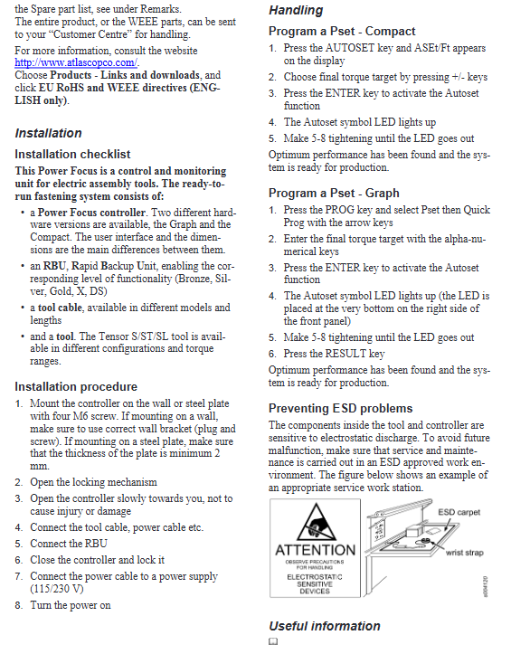
ESD electrostatic protection
The internal components of controllers and tightening tools are highly sensitive to electrostatic discharge. Maintenance and disassembly operations must use anti-static workstations: anti-static floor mats+anti-static wrist straps, with standard workstation diagrams attached to the document; Not working in an anti-static environment can cause unknown equipment malfunctions.
Guidelines for Human Machine Engineering Operations
Used to reduce the risk of operator injury:
Regularly rest and change the posture of the workstation; Workstation adaptation homework content; Place tools and materials within a comfortable reach.
Try to avoid working above shoulder height as much as possible; Use torque arms and balancers for high-altitude operations, with tools close to the body to reduce muscle static loads.
Avoid extreme force postures on the wrists and arms; Ensure sufficient lighting.
Wear hearing protection in noisy environments; Use high-quality sleeves to reduce vibration.
Response torque protection standard ISO11148-03: Handheld tools>10 Nm, straight handled tools>4 Nm, must be equipped with torque arms/reaction bars to absorb reaction forces.
Install dust removal equipment or protective masks for dust working conditions.
Technical parameters
Item Parameter
Power supply single-phase AC 90-120 V/180-240 V, 50-60 Hz; automatic recognition of input voltage
Indoor use under environmental conditions; The highest altitude is 2000 meters, and the highest ambient temperature is 40 ℃; Humidity: ≤ 31 ℃, maximum 80% RH, linearly decreases to 50% RH at 40 ℃; overvoltage category II, pollution level 2
Power consumption standby uniform 20 W; S4/S7/ST3-6/SL tool no-load 150 W; S9/ST8-10 no-load 200 W
Recommended insurance S4/S7, etc.: 110V-15A, 230V-10A; S9 series: 110V-20A, 230V-16A
Power supply wiring brown/black live wire; Blue zero line; Yellow green – protective grounding
The power supply load can be manually started and stopped on a single machine, and up to 3 controllers can be connected to the same circuit; Under multi axis synchronous working conditions, each controller requires an independent power supply circuit.
Maintenance, spare parts and warranty
Maintenance can only be completed by trained and qualified personnel, and only Atlas Copco original spare parts can be used. Without an order number, the internal parts of the repair kit are not sold separately to the outside world; If non original parts are used, the manufacturer has the right to void all warranties.
Effective conditions for warranty: The equipment must be installed, operated, lubricated, and overhauled strictly in accordance with the manual; If it is detected that the motor has been disassembled without authorization, all warranty will be lost directly.
ServAid tool software (web/CD): can access security documents, disassembly explosion views, spare parts ordering, support new and old product retrieval, and is available in multiple languages.
Equipment identification symbol
CE: Complies with the EU Machinery Directive;
Triangle exclamation mark: Be careful when operating;
Cross the trash can: WEEE electronic waste needs to be specifically recycled;
Reading manual icon: Before starting up and using, it is necessary to read the product manual.
Scrap and recycle
After the equipment reaches its service life, disassemble the components and recycle them according to local regulations; The battery will be handed over to the designated national battery recycling agency for disposal.