KUKA LBR iisy 3 R760 Assembly Manual
Product Description
Hardware composition of the main body
Base, A1 rotating column, A2 connecting rod arm, A3 large arm, A4-A5-A6 inline wrist, Commander wrist unit, all cables integrated internally.
Commander wrist unit: LED status light, dual enable switch, rewind button, control knob OK button, drag and drop handle; Equipped with external interface A6.
Permitted Use and Prohibited Misuse
Allow: moving tooling workpieces, processing, and material transportation, meeting environmental conditions, and following maintenance cycles. ❌ Prohibited: Climbing, carrying people and animals, outdoor activities, explosion-proof hazardous areas, radioactive and underground mining, unauthorized use will result in loss of warranty.
Core Technical Parameters
Project parameters
Number of axes: 6 axes
Rated load 3 kg; maximum load 3.34 kg (center of gravity zero point only)
Maximum arm span 760 mm
The self weight of the body is 22.8 kg
Repetitive positioning accuracy ± 0.1 mm
Protection level: IP30 for the whole machine
Installation method: Ground, ceiling, wall, any inclination angle (± 180 °)
Working temperature+5~+45 ℃; Storage -25~+70 ℃
Humidity 20-80%, no condensation
The range of motion for each axis is A1 ± 185 °; A2‑230~+50°;A3±150°; A4±175°; A5±110°; A6±220°
Under rated load, the rotational speed is 200 °/s for A1-A3, 300 °/s for A4-A5, and 400 °/s for A6
Zero point calibration A1=0 °; A2=-90 °; A3=90 °; A4=0 °; A5=0 °; A6=0 °
Transport attitude A1=0 °; A2=-115 °; A3=140 °; A4=0 °; A5=50 °; A6=0 °
Wrist flange: ISO 9409-1-50-7-M6, 8 × M3 thread, locating pin φ 3H7; Provide the allowable axial force, radial force, and overturning torque for flanges under normal operation and emergency stop conditions.
Base load: Provide vertical force, horizontal force, and overturning moment for three working conditions: ground/ceiling/wall; The base must be checked according to the load, and failure of the base will cause it to overturn and collapse.
Stopping distance and time: distinguish between Stop0 (hard cut-off brake closure, causing significant damage to the robot, recommended for less use, brake testing every year) and Stop1 controlled shutdown; Provide stopping angle/time charts for A1/A2/A3 under different elongation rates and loads.
The QR code on the nameplate is linked to KUKA Xpert, and the warning label on the nameplate must not be torn off; Compliant with REACH Article 33 substance notification.
Planning and design, mechanical installation, cable interface
Planning considerations
The following operating conditions will accelerate component wear and require shortened maintenance cycles or consultation with KUKA services: long-term operation at extreme temperatures, abrasive dust environments, continuous approach to performance limits, full power start of refrigeration units, single axis high-frequency start stop, long-term static vertical posture, and external continuous process forces; The device has automatic shutdown protection against overheating.
Cannot be used in environments with conductive dust and condensation.
Rack Installation
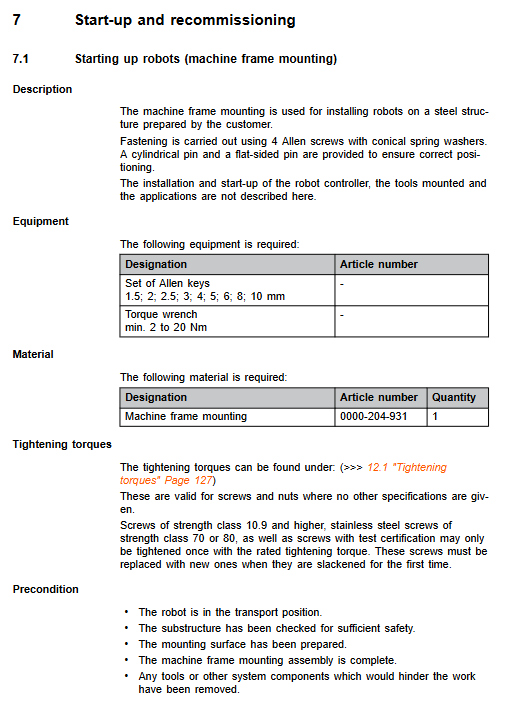
Install components using a rack with locating pins, and tighten 4 M8-8.8 bolts diagonally in multiple stages; Positioning pin ensures installation positioning; The flatness and roughness of the installation surface meet the requirements of the drawings.
Non ground tilt installation (ceiling/wall) must input the actual tilt angle into the controller software. Parameter errors can cause overload and accidental damage to the robot.
Interfaces and Cables
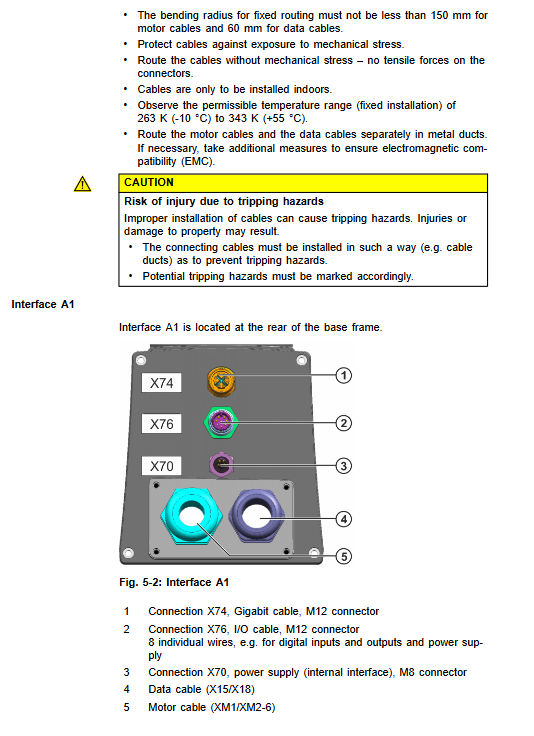
Base A1 interface
X74: Gigabit M12;
X76: M12 IO interface (24V DI/DO);
X70: M8 internal power supply;
X15/X18 data cable; XM1/XM2-6 motor cable; Protect the grounding terminal M4.
Wrist A6 (Commander) external interface (optional X94/X96 connector pack)
X94 Gigabit; X96:24V power supply+digital input/output, maximum cable length of 0.5m; used for external clamp. three Cable specifications
The standard cable is 7 meters long, with a maximum total length of ≤ 25 meters; a maximum of 1 connector splice is allowed;
Fixed laying bending radius: motor cable ≥ 150 mm; data cable ≥ 60 mm;
Separate the wiring of motor cables and data cables; Indoor installation; Equipotential protection grounding must be done, with a PE conductor of 4mm ².
Transportation and commissioning start
Transportation: must enter the designated transportation posture; Use qualified lifting equipment to avoid impact and vibration; The outer dimensions of the packaging box are 800 × 600 × 620 mm; remove the transportation protective components.
Start operation steps
Confirm that the robot is in transport position and the base structure strength is qualified;
Installation of positioning pin, vertical positioning, diagonal step-by-step locking of M8 bolts;
Connect the protective equipotential ground wire with a torque of 2.8 Nm;
Connect motor cables and data cables; Check the locking of the connector;
Install tools, complete power on, zero calibration, and load parameter input according to the controller manual;
The load mass, center of gravity, and inertia must be entered into the controller, and torque monitoring and collaborative safety functions depend on these parameters.
Disabled manual mobile manipulator: limited to emergency rescue in accidents, directly opposing the brake to push the joint.
Maintenance chapter
Only maintenance specified in the manual is allowed, and all other repairs must be authorized by KUKA personnel; Use original spare parts; Once the high-strength bolt is loosened, it must be replaced with a new one.
maintenance cycle
After 100 hours of operation, check the torque of all fasteners;
5000 hours or at the latest 1 year: replace A5 synchronous toothed belt;
7-year comprehensive inspection of the entire machine, contact KUKA service.
A5 synchronous belt replacement complete process
Safety: Emergency stop locking device; Fix the A5 joint to prevent rotation; Remove the toothed belt cover;
Loosen the adjusting screw and remove the old toothed belt; Assemble a new synchronous belt;
Use a frequency meter TSM alpha-2 to measure the vibration frequency, with a target of 155 ± 5 Hz;
Move the joint for retesting and verify the tension multiple times; Reinstall the protective cover; Complete A5/A6 zero calibration; T1 low-speed trial operation.
Robot cleaning: power off; Prohibit high-pressure water guns and compressed air from blowing bearing seals; Use solvent-free, non corrosive water-soluble cleaning agents; Perform anti-corrosion protection after cleaning.
Repair
Replacement of shell cover: Each joint shell can be disassembled and assembled separately; All use TORX plum blossom screws and buckle structure; Strictly cut off power and lock during disassembly and assembly; Perform electrical safety steps 5; Replace completed T1 mode test motion.
Repairs beyond the document must be handed over to KUKA services; Spare parts require a maintenance card to be filled out, and faulty parts should be sent back to the warehouse card.
Retirement, storage, and scrapping
Retired and dismantled: the robot switches to a transport posture; Power off, disconnect all cables; Remove the fixing bolts and lift the base vertically.
Storage: Clean, sealed and protected, avoiding condensation and direct sunlight, temperature and humidity meet specifications.
Scrap: Classify and dispose of according to local regulations; The manual lists all materials: aluminum alloy, copper, steel; Various electronic components and motors; Plastic ABS/PTFE; Seals, lubricating grease, adhesive sealant.
Optional Accessories Options
Co Act ESG C K060 servo two finger gripper: electric parallel gripper; Finger kit included; 24V power supply, occupying DI/DO; Provide disassembly and assembly steps;
Output flange: ISO9409 standard flange, removable to increase effective load;
External centering adapter;
X94/X96 connector package: A6 external distribution connector for wrist, leading out gigabit network and IO power supply;
Optional supporting cables: IO cable, gigabit cable, external protective ground wire.