Aerotech Ndrive HPe 10/20/30 High Performance PWM Digital Servo Drive
Product Overview
1.1 Model Electrical Parameters
Model Peak Current Continuous Current
HPe10 10A 5A
HPe20 20A 10A
HPe30-S 30A 10A (standard with built-in 40W discharge resistor – S)
Power supply: Control power supply and motor power supply with two independent AC inputs of 85-240VAC, 50-60Hz; Motor DC bus 20-340VDC; PWM switching frequency 20kHz; The maximum servo bandwidth is 2500Hz, and the efficiency is 85-95%.
Supporting motors: brushless servo, brushed DC, two-phase stepper motor.
Minimum load inductance: 0.1mH@160VDC ; 1mH@320VDC .
Hardware protection: output short circuit, peak overcurrent, RMS effective value overcurrent, bus overvoltage, overheating, control power undervoltage, power stage bias undervoltage; Control side and power side optocouplers+transformer isolation.
Environmental conditions: working temperature 0-50 ℃; Storage -30~85 ℃; Humidity ≤ 80% RH (non condensing); The highest altitude is 2000m; pollution level 2, only for indoor use in the cabinet.
Mechanical dimensions:
Slim without IO board: 2.27kg;
Equipped with IO board: 2.45kg; equipped with RDP rotary board: 2.45kg;
Install M4 screws; Reserve 25mm ventilation around and 100mm operating space on the wiring side.
1.2 Onboard native hardware resources
Communication: 3-channel FireWire; J204 Ethernet (ENET option); J206 RS-232 has no functionality on HPe.
J207 motor feedback 25 pin D-SUB: main encoder, Hall sensor, PTC motor thermal sensor, CW/CCW limit, Home return to zero, brake output. Onboard+5V/500mA encoder power supply.
J205 auxiliary I/O (26 pin D-SUB): second auxiliary encoder; 4-channel optocoupler DI; 4-channel optocoupler DO; 2-channel 50ns high-speed differential input; 1 channel 16 bit differential analog input ± 10V; 1 channel 16 bit analog output ± 10V; multiplexed pin as single axis PSO output.
TB201 ESTOP emergency stop detection input; TB202 brake power terminal, onboard solid-state brake relay (24VDC/2.5A).
1.3 Overview of Ordering Options
Function Description of Options
IO/IOH expansion IO board, 16 isolated DI/16 isolated DO; 3 channels of 16 bit AI, 3 channels of 16 bit AO; Mechanical brake relay; SSINet; Optical isolation PSO output
MXH simulation sine cosine encoder interpolation, up to x 65536; Support outputting interpolated orthogonal encoder signals; Support multi axis PSO
DUALPSO/TRIPLEPSO dual axis/three-axis vector PSO, must be paired with IO board, relying on SSINet to transmit encoder data of each axis
PSONC PSO output normally closed mode (default normally open)
ENET 10/100M Ethernet, only third-party IO expansion, cannot replace FireWire sports bus
– S has a built-in 50 Ω/40W discharge resistor; HPe30 standard configuration; Exclusive with EXTSHUNT
EXTSHUNT TB103 external discharge resistor terminal; Use of high inertia and high regenerative energy systems
RDP1-xxK/RDP2-xxK single/dual channel rotary transformer interface board, carrier 5/7.5/10kHz
1.4 Compliance Certification
CE(EMC 2014/30/EU、LVD 2014/35/EU、RoHS2); TUV‑SUD NRTL UL61010‑1。
Important safety: There is high voltage inside the drive after power failure; The temperature of the discharge resistor casing is greater than 70 ℃; The system integrator is responsible for the grounding of the entire machine and the safe return of external emergency stops.

Installation and hardware wiring configuration
2.1 FireWire Device Address Settings
Dial S1 to set the unique device number 1-32 for the driver, which corresponds one-to-one with the A3200 axis number; A single FireWire daisy chain can have up to 16 axes, while the entire machine can have up to 32 axes; The maximum length of copper cable is 4.5m, and fiber optic repeaters are used for long distances.
2.2 Power terminals
TB101 control power supply (85-240VAC): After the emergency stop cuts off the motor power supply, the power supply does not cut off, maintaining communication and feedback (keep alive function).
TB102 motor power supply: AC input, A/B/C three-phase motor power output; External delay fuse is required; Grounding must be protected.
Transformer selection: TV/TM series isolation transformer, capable of outputting 40/80/160/320VDC DC bus; TM3/TM5 transformer can supply power to up to 4 HPe units at most.
EXTSHUNT external discharge resistor TB103: The bus is automatically connected for discharge at approximately 380VDC; The manual provides a formula for calculating regenerative energy, which is used for selecting large inertia systems.
2.3 EMC/CE wiring mandatory requirements
Motor cables must be shielded, and the shielding layer must be grounded for protection; The D-SUB connector uses a metal shell for crimping and shielding.
Power cables and encoder/IO signal lines are physically separated and routed.
Mandatory installation of Aerotech UFM-ST power filter on AC input end; Install designated ferrite magnetic rings on motors and FireWire cables.
The driver is a component, and the final whole machine needs to undergo a complete EMC test.
2.4 Motor wiring and phase setting
Supports brushless, brushed DC, and two-phase stepper motors, with Aerotech’s original motors directly using matching cables; Third party motors must be phase modulated, and two sets of phase modulation methods are provided:
Live phase modulation: Motor Phasing Calculator tool for A3200 configuration manager, Nstat software to view Hall status.
Power off oscilloscope phase adjustment: measure the motor back electromotive force and Hall timing, and verify the phase alignment relationship.
Brushless motor: Hall HA/HB/HC connected to J207; Hall all 0s or all 1s are Hall faults.
Brushed DC motor: connected to A/C, with vacant B terminal; Measure the polarity of the back electromotive force of the manual motor to determine the direction of rotation.
Two phase stepper motor: connected to A-B C; The encoder must verify the phase.
2.5 J207 main feedback 25 pin D-SUB connector
integrate:
Encoder interface: Standard RS-422 TTL differential encoder; MXH option supports analog sine and cosine encoders; Supports EnDat serial absolute encoder.
Hall input (brushless motor).
PTC thermistor motor overheating detection, triggering overheating fault when resistance>1k Ω.
CW/CCW positive and negative limit switches, Home reset switch, software configurable normally open/normally closed; Reverse limit connection phenomenon: It can collide with the limit but cannot exit.
Encoder fault input; Output of onboard brake solid-state relay.
2.6 J205 Auxiliary I/O (26 pin D-SUB)
The second RS-422 auxiliary encoder channel is used for handwheel, master-slave tracking, and dual closed-loop; Not supported – MXH analog encoder.
Single axis PSO output: reuse auxiliary marker ± differential pins; RS-422 differential output; The maximum tracking rate is 16.6MHz with a delay of 160ns.
4-channel ordinary DI, 4-channel ordinary DO; 2-channel 50ns high-speed differential input In12/In13 (external event capture).
1 differential analog input ± 10V; 1 analog output ± 10V.
IO supports source sourcing/irrigation signaling, and the same group must be unified; Inductive loads must be connected to current diodes.
2.7 TB201 ESTOP emergency stop input
Only used as a signal detection port, cannot cut off the motor power itself! 5-24V input; Only report faults; A truly safe shutdown requires an external relay to cut off the AC power supply to the TB102 motor, while keeping the TB101 control power supply powered on; Axis parameter FaultMask enables ESTOP fault; Add RC/varistor to the relay coil to absorb surges.
2.8 Two wiring schemes for holding brake
Use motherboard TB202 power supply+J207 solid-state relay output;
Use IO expansion board TB301 mechanical relay;
Two sets of brake relays are prohibited from being activated simultaneously, choose one from the other.
IO expansion board hardware
Add TB301~TB308 terminals after installing IO:
TB301: Mechanical brake relay; Jumper JP3 modifies the polarity of the brake switch.
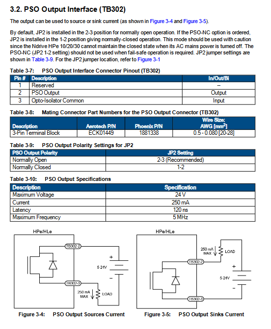
TB302: Optically isolated PSO output; JP2 jumper setting PSO normally open/normally closed; Maximum 250mA, maximum 5MHz.
TB303: 4-channel 16 bit analog output (AO0 and motherboard J205 AO0 hardware are connected in parallel and cannot be wired at the same time).
TB304: 4-channel 16 bit differential analog input (AIN0 and mainboard J205 AIN0 hardware parallel).
TB305/TB306:16 isolated digital input, built-in onboard+5V user power output.
TB307/TB308:16 isolated digital outputs, maximum 60mA per channel; source/fill mode configurable.
J302/J303 SSINet high-speed communication port: realizes encoder data forwarding between multiple drivers, and realizes dual/three-axis PSO of DUALPSO/TRIPLEPSO.
Multi axis PSO networking logic: The X-axis serves as the PSO host and receives Y-axis and Z-axis encoder data through SSINet. SSINet cables J302-J302 are interconnected; Send axis SSI is configured as output, and receive axis is configured as input.
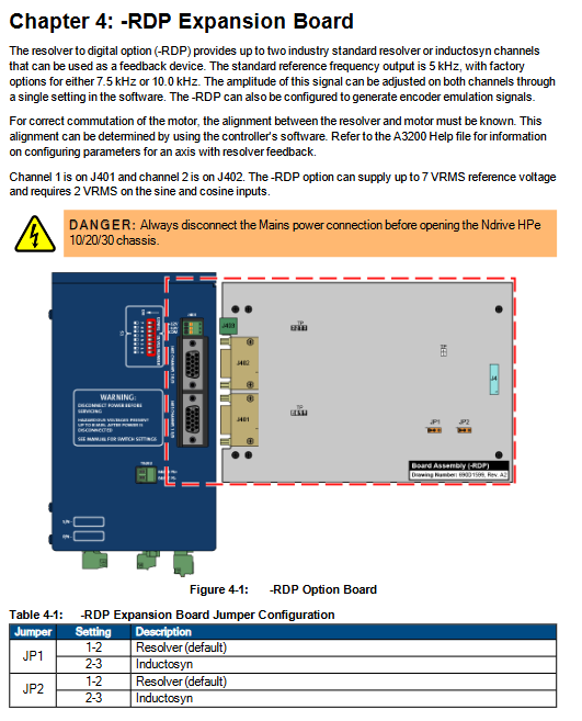
RDP Rotary Transformer Option Board
J401/J402: Single/dual channel rotary transformer input; J403 rotary power supply.
Hardware jumper configuration with carrier frequency of 5/7.5/10kHz; The manual provides the steps for rotary transformer wiring, zero calibration, and testing points.
Accessories
Complete set of supporting cable part numbers: motor cable, feedback cable, FireWire copper/fiber optic cable, SSINet cable.
Connection scheme for joystick and electronic handwheel: can be connected to J205 auxiliary IO or IO expansion board IO port; The BBA32 module is used for handwheel signal conversion.
Maintenance chapter
Definition of LED status indicator: PWR power supply, EN enable, FAULT fault, MARK encoder zero mark.
Control board, power board jumper, fuse part number, backup battery specifications.
Preventive maintenance: Regularly clean the cooling air duct, tighten the connector, and check the cable shielding grounding.