Leybold TTR 101 series vacuum transmitter
Product positioning and model differentiation
The Leybold THERMOVAC TTR 101 series is a dual sensor composite vacuum transmitter used for clean gas vacuum measurement. There are three models in total:
TTR 101: Basic type, no switch output, optional display screen
TTR 101 S2: with 2 programmable switch points (SP1/SP2)
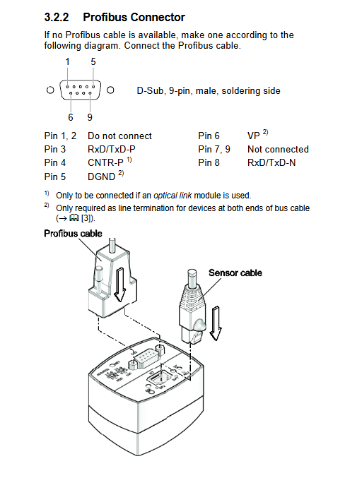
TTR 101 PB: with Profibus DP communication+2 switch points
Vacuum interface: DN 16 ISO-KF/⅛ “NPT
Core technical parameters
Measurement performance
Parameter indicators
Measurement range 5 × 10 ⁻⁵… 1500 mbar
Measurement principle 5e-5~1 mbar: Pirani; 10-1500 mbar: capacitor film
Accuracy (N ₂) 950-1050 mbar: ± 2.5%; 100~950 mbar:±5%
Repetitive accuracy ± 2% (1e-3~1100 mbar)
Response time<30 ms
Output signal 0~10.23 V logarithmic output, 1.286 V/decade doubling
Electrical and Environmental
Parameter indicators
Supply voltage+15…+30 VDC (Class 2/LPS)
Power consumption without Profibus: ≤ 2.5 W; With Profibus: ≤ 3 W
Switch capacity<30 VAC/DC, ≤ 0.3 A (resistive)
Working temperature+10…+50 ℃
Storage temperature -20…+65 ℃
Protection level IP40
Weight<120 g (without bus); <250 g (with Profibus)
Gas correction factor (Pirani segment<1 mbar)
table
Gas coefficient C Gas coefficient C
H ₂/Water Vapor 0.5 Air/N ₂/O ₂ 1.0
He 0.8 Ar 1.7
CO₂ 0.9 Kr 2.4
Working principle
High voltage section (10-1500 mbar): Only capacitive thin film sensors are used, regardless of the type of gas
Low pressure section (5e-5~1 mbar): only use Pirani sensor, gas correction required
Intermediate section (1-10 mbar): Dual signal proportional fusion output
Installation requirements
Vacuum connection
Maximum pressure resistance: 5 bar (absolute pressure), burst pressure 10 bar
Installation direction is arbitrary, it is recommended to prevent condensation from entering horizontally/vertically
Conductive clamps must be used for reliable grounding, following EN 61010
electrical connection
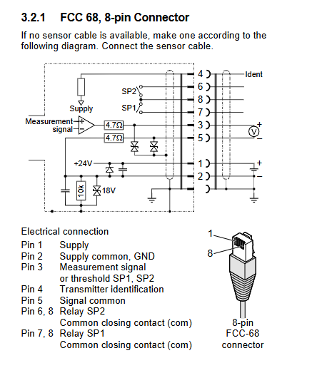
Standard version: 8-pin FCC 68 connector
Profibus version: 9-pin D-Sub, speed * * ≤ 12 Mbaud * *, address 0-125
Shielded wire single ended grounding to avoid ground loop interference
Safety taboos
Prohibition of measuring flammable and explosive mixed gases containing oxidants
Ceramic sensors have poor impact resistance and are strictly prohibited from falling or bumping
Operation and Display
Status LED
ST green light: measurement mode
ST red light/flashing: malfunction
SP1/SP2 green light: switch closed
LCD display
Real time pressure, unit, measurement principle, switch status
Fault code: FAIL PIR1/CAP1/EEPROM/SENSOR
Switch function (S2/PB version)
Setting range: 5e-5~1500 mbar
Delay: 10% threshold
Mode: Low trigger/High trigger/Dual point trigger (only Profibus can be set)
Calibration and maintenance
Two-point calibration
ATM calibration: Atmospheric pressure>100 mbar, calibrated to 1000 mbar
HV calibration: Vacuum<1e-5 mbar, calibrated to 5e-5 mbar
Maintain rules
Drift caused by pollution requires regular calibration
Filaments and sensors are consumables and are not covered by warranty
Users are prohibited from disassembling and repairing the machine, otherwise the warranty will become invalid
Sensor replacement
Loosen the 2mm hex socket screw, insert and remove it vertically, and do not twist it
After replacement, recalibration is necessary
Troubleshooting (key)
Possible causes and solutions for the fault phenomenon
Output=0V, ST red light sensor/cable fault check, restart, replace sensor
FAIL PIR1 Pirani malfunction sensor replacement
FAIL CAP1 capacitor diaphragm fault, replace sensor
FAIL EEPROM storage failure, restart invalid, return to factory
Key questions and answers
What measurement principle does the TTR 101 series use, and which sensors are used for different ranges?
Answer: Adopting Pirani+capacitance film dual sensor composite measurement; Use Pirani sensors for 5 × 10 ⁻⁵~1 mbar, capacitive thin film sensors for 10~1500 mbar, and dual signal fusion range for 1~10 mbar.
How to calibrate TTR 101 and what two conditions must be met?
Answer: Perform two-point calibration: ① ATM calibration needs to be completed at atmospheric pressure>100 mbar; ② HV calibration needs to be completed under vacuum<10 ⁻⁵ mbar; After calibration, it is necessary to confirm that the output of approximately 4.85 × 10 ⁻⁵ mbar is normal.
What is the core difference between TTR 101 S2 and TTR 101 PB, and what are the limitations of the switch output?
Answer: S2 is a 2-channel switch version, PB adds Profibus DP communication; The switch is a solid-state relay, rated * *<30V, ≤ 0.3A * *, with a fixed hysteresis threshold of 10%. The dual point trigger mode can only be set through Profibus.