Omron C500 series rack mounted PLC
The installation manual (W132E13D) for Omron C500 series rack mounted PLC, revised in 1997, fully explains the system composition, rack/module/power/memory installation specifications, I/O wiring, environmental requirements, power design, noise protection, safety measures of this modular PLC, clarifies the CPU rack+extended I/O rack architecture, maximum 512 point I/O, supports AC100-240V/DC24V dual power supply, 5 types of I/O module shapes, and various special functional modules. It provides detailed wiring examples, fault protection, and consumables replacement processes, and is the official basis for equipment installation, electrical debugging, and maintenance.
System composition and architecture
C500 is a rack mounted card structure consisting of a CPU system and an expansion system.
CPU rack
Backboard: 3/5/6/8/9 slots available for selection
Core components: CPU unit, CPU power supply, I/O control unit, I/O unit
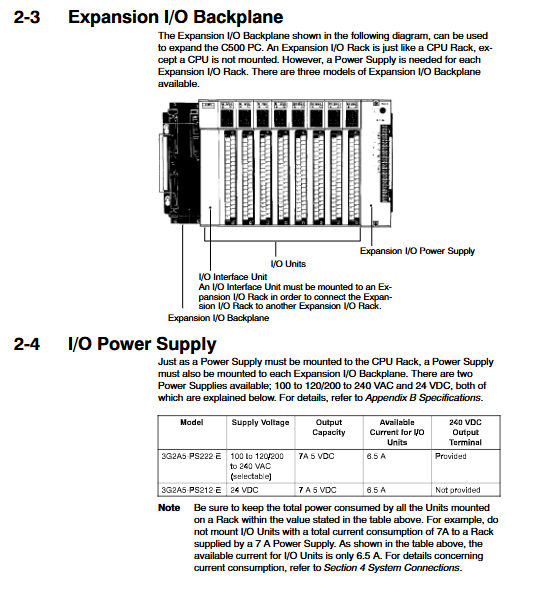
Expand I/O rack
Backboard: Expansion specific
Components: I/O interface unit, expansion power supply, I/O unit
Maximum configuration
Connect up to 3 expansion racks
Maximum I/O points: 512 points
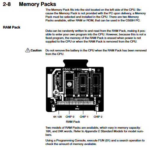
memory
RAM package: Supports 16K/24K words, battery needs to be maintained during power failure
ROM package: equipped with EPROM chip, program is not lost in case of power failure
Module and power specifications
1. Power supply unit (key parameters)
Model Power Supply 5V Output I/O Available Current 24V Auxiliary Output
3G2A5-PS221-E AC100-240V 7A 5A 0.8A
3G2A5-PS223-E AC100-240V 12A 10A None
3G2A5-PS213-E DC24V 9A 5A None
3G2A5-PS222-E AC100-240V 7A 6.5A 0.8A
3G2A5-PS212-E DC24V 7A 6.5A None
2. Classification of I/O units
Appearance: 5 different structures A/B/C/D/E
Input: DC24V, AC100-120V, AC/DC universal TTL
Output: Relay, transistor, bidirectional thyristor
Special I/O: AD/DA, high-speed counting, position control PID、 Link unit
3. Module power consumption (typical value)
Input unit: 0.01~0.34A
Output unit: 0.1~0.46A
Special Unit: 0.3~1.4A
Installation and environmental requirements
Installation method
Must be installed vertically, with the CPU rack on top
Rack spacing: 70~120mm
Expansion cable: Single cable up to 2m in length, total length ≤ 12m
Environmental restrictions
Temperature: 0~55 ℃
Humidity: 10%~90% RH (no condensation)
Vibration: 10~55Hz, 0.5mm, 2G
Impact: 10G, 3 times
Wiring and noise resistance
The distance between strong current and I/O lines is ≥ 300mm
Shielded twisted pair cables must be used
Grounding resistance: ≤ 100 Ω, wire diameter ≥ 2mm ²
System wiring specifications
Power wiring
AC power supply: supports 100-120V/200-240V switching
Terminal torque: 1.2N · m
Circuit breakers must be installed
I/O wiring
Wire gauge: AWG22~18 (0.3~0.75mm ²)
Cold pressed terminals must be used and bare wires are prohibited
Terminal torque: maximum 8kg · cm
safety protection
Inductive load: parallel surge absorber/diode
Leakage current: Input/output with discharge resistor
Interlock: The forward and reverse rotation of the motor must be interlocked with external hardware
Power supply and power outage handling
Power failure response
Power outage ≤ 10ms: ignored
10-25ms: Possible shutdown
25ms: Stop output, automatically restart after recovery
Grounding requirements
Reasonable connection between LG and GR terminals enhances noise resistance
Grounding and strong current system are independent
Safety precautions
Mandatory Security
Power off operation: plugging and unplugging modules, wiring, and replacing accessories
Prohibit touching terminals with live electricity and disassembling modules
system security
Emergency stop requires external hard wiring
Key circuits provide dual safety mechanisms
Maintenance and consumables replacement
battery
Lifespan: 4 years (25 ℃)
Replace within one week after reporting the alarm
Replacement time: ≤ 5 minutes
fuse
Specification: 3A/250V (MF61NR)
Replacement requires power-off operation
relay
Electric lifespan: 300000 times (resistive), 100000 times (inductive)
CPU core specifications
Project parameters
71 types of instructions (12 basic+59 special)
Execution speed basic instruction 3-18 μ s
Maximum memory of 24K words
512 I/O points
Timer/counter 128 points
Isolation withstand voltage 1500VAC for 1 minute
Key issues
Question 1: What are the limitations of the C500 PLC’s expansion architecture? What are the maximum I/O points and expansion rules?
Answer: Adopting a CPU rack+extended I/O rack structure; Up to 3 expansion racks can be expanded, with a maximum length of 2m for a single expansion cable and a total length of ≤ 12m. The system supports a maximum of 512 I/O points; The CPU rack needs to be equipped with an I/O control unit, and each expansion rack must be equipped with an I/O interface unit.
Question 2: What are the mandatory safety requirements for wiring and grounding of C500 PLC? What are the consequences of non-compliance?
Answer: Cold pressed terminals must be used, and the terminal torque must meet the standard; The distance between the strong current and the I/O line is ≥ 300mm; the grounding resistance is * * ≤ 100 Ω * *, the wire diameter is ≥ 2mm ², and it is independently grounded. Failure to comply may result in interference, system crashes, erroneous outputs, electrical leakage, and module breakdown.
Question 3: What are the battery and fuse specifications for C500? What are the key time requirements for replacement?
Answer: The battery has a lifespan of 4 years and must be replaced within 1 week after an alarm. Replacement should be completed within 5 minutes to prevent program loss; Fuse specification 3A/250V (MF61NR), replacement must be completely powered off.