Microchip dsPIC30F series 16 bit high-performance digital signal controller
Product positioning and core architecture
DsPIC30F is a 16 bit high-performance digital signal controller (DSC) launched by Microchip, which integrates MCU control capabilities and DSP computing capabilities, and adopts an improved Harvard architecture:
Instruction bit width: 24 bits
Data bit width: 16 bits
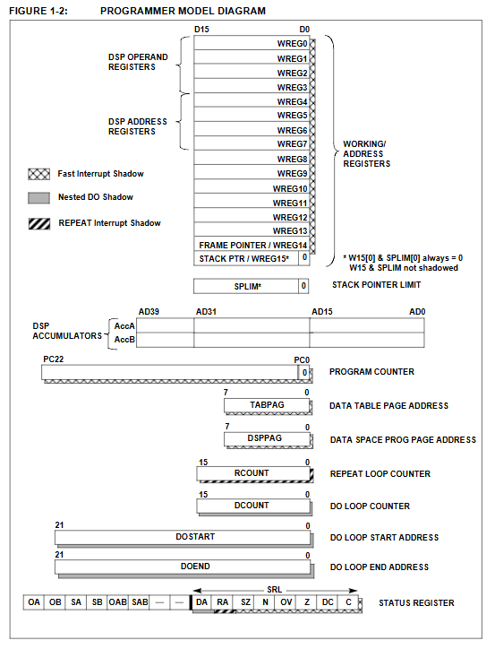
Working register: 16 x 16 bits
Program counter: 23 bits, maximum addressing 4M x 24 bits
Performance: Up to 30 MIPS, clock input DC~120MHz
CPU core characteristics
Computational unit
16 × 16 bit single cycle hardware multiplier
Dual 40 bit accumulator (with saturation logic)
40 level barrel shifter (can move 15 positions to the right/16 positions to the left in a single cycle)
Single cycle MAC (multiply accumulate) operation
Interrupt system
Interrupt source: up to 32
Abnormal vectors: 15 (8-level interrupt+7-level trap)
Priority: Level 8 programmable
Delay: Normal 3 cycles, fast interrupt 1 cycle
Storage configuration (maximum value)
Storage Type Capacity
Program Flash 144KB
Data RAM 8KB
EEPROM 4KB
64KB linear addressing data space
Key parameters of DSP engine
Module indicators
Multiplier 16 × 16 bits, single cycle
Accumulator 2 x 40 bits, saturated/rounded
Shifter 40 levels, single cycle shifting
Dual data read support (dual AGU)
Loop buffer hardware module addressing
Bit reversal addressing supports FFT optimization
Peripheral functions
Simulate peripherals
10 bit ADC: 16 channels, 500ksps, sleep convertible
12 bit ADC: 16 channels, 100ksps, sleep convertible
LVD low voltage detection, BOR power-off reset
timer
5 16 bit timers, of which 4 can be combined into 2 32-bit timers
Timer1 supports 32kHz RTC
Motion Control
Motor control PWM: up to 8 outputs, 16 bit precision
Orthogonal encoding interface QEI: x2/x4 counting, input filtering
communication interface
SPI: 3-wire, supports 4 modes
I2C: master/slave, 7/10 bit address
UART: Address wake-up, Start bit wake-up
CAN: 2.0B protocol, up to 1Mbps
DCI: Supports I ² S and AC’97 audio protocols
I/O port
Up to 54 programmable I/O channels
25mA sink/source driving capability per channel
Partial support for change interruption
Power and Power Management
Working voltage: 2.5V~5.5V
Power consumption mode:
SLEEP (sleep mode)
IDLE (idle)
Slowdown
Built in power on reset (POR), power on timer (PWRT), oscillator stabilization timer (OST)
Exception handling and reset
Exception Type
reset
Traps (7 types: oscillator failure, stack error, address error, arithmetic warning, software trap, etc.)
Interrupt (Level 8 priority)
Reset source
Power on reset POR
External MCLR reset
Watchdog WDT reset
Power off reset BOR
Command reset
Development toolchain
MPLAB IDE v6.0: Integrated Editing/Compilation/Debugging
MPLAB C30: ANSI C Optimized Compiler
MPLAB SIM: Instruction Level Software Simulator
MPLAB ICE 4000: Online Real time Simulation
MPLAB ICD 2: Online Debugging+Programming
PRO MATE II: Universal Mass Production Programmer
Key questions and answers
Question 1: What are the core advantages of dsPIC30F compared to traditional 16 bit MCUs? What are the key hardware supports?
Answer: The core advantage is that it has both the control capability of MCU and the high-speed computing capability of DSP, which can realize complex algorithms and real-time control on a single chip. Key hardware: single cycle 16 × 16 multiplier, dual 40 bit accumulator, dual address generation unit (AGU), 40 level barrel shifter, supporting single cycle MAC operation and parallel data reading.
Question 2: What are the key parameters of the interrupt system for dsPIC30F? What is the significance of rapid interruption?
Answer: Key parameters: up to 32 interrupt sources, 15 exception vectors, and 8 levels of programmable priority; Normal interrupt has a delay of 3 cycles, while fast interrupt has a delay of 1 cycle. Fast interrupts are used in extremely real-time scenarios such as motor overcurrent protection and high-speed sampling, which can compress response time to the minimum and avoid control failure.
Question 3: What specialized peripherals does dsPIC30F provide for motor control? What functions do they respectively undertake?
answer:
Motor control PWM module: generates synchronous multi-channel PWM, supports three-phase motor drive, dead zone control, and fault protection.
Orthogonal Encoding Interface QEI: Read the encoder position and velocity to achieve closed-loop servo control.
High speed ADC: synchronously samples current/voltage to achieve vector control and overload protection.
The combination of the three can achieve high-performance servo drive for BLDC, permanent magnet synchronous, and induction motors on a single chip.