OMRON SYSMAC CPM1A series programmable controller
Basic product information
Omron CPM1A is a compact high-speed PLC designed for small control systems with 10-100 I/O. It is divided into V1 version and Pre-V1 version, and the V1 version is fully compliant with EC directives.
Program capacity: 2048 words
Instruction types: 14 basic instructions, 77 special instructions (135)
Instruction execution speed: Basic instruction 0.72-16.2 μ s
Backup method:
Flash: User Program, Read Only DM Area, PC Settings
Internal capacitance: Read/write DM area, HR area, counter, backup for up to 20 days at 25 ℃
Hardware specifications and composition
(1) CPU Unit Model
I/O point input/output power supply model suffix
10:6:4:00am AC/DC 10CDR/10CDT/10CDT1
20:12:08:00 AC/DC 20CDR/20CDT/20CDT1
30:18:12pm AC/DC 30CDR/30CDT/30CDT1
40 o’clock 24 o’clock 16 o’clock AC/DC 40CDR/40CDT/40CDT1
(2) Expansion Unit
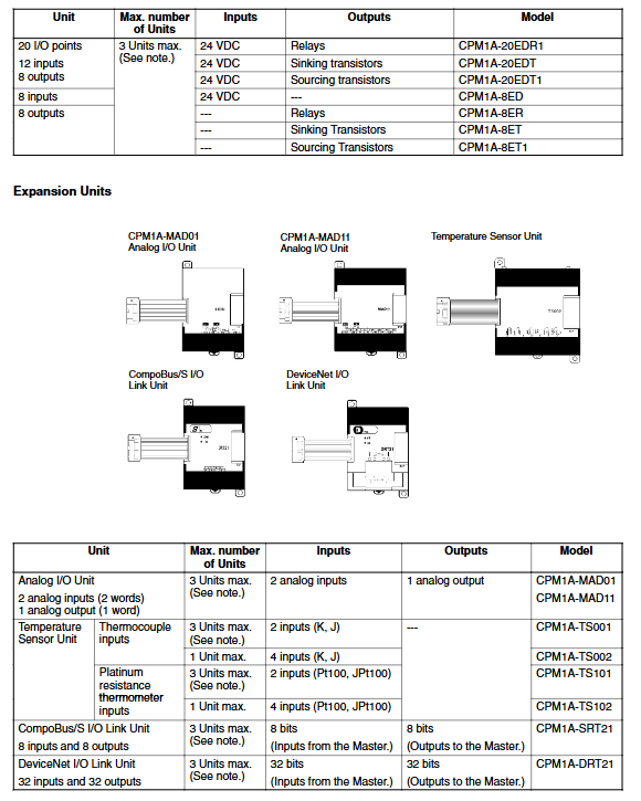
Maximum expansion: 3 expansion units, 30/40 point CPU can be expanded to 100 point I/O
Type: I/O Expansion, Analog I/O, Temperature Sensor, CompoBus/S, DeviceNet Unit
Analog quantity: up to 6 inputs and 3 outputs, resolution 1/256~1/6000
(3) Environmental and electrical parameters
Working temperature: 0~55 ℃, humidity 10%~90% (no condensation)
Power supply: AC 100~240V, DC 24V
Grounding: ≤ 100 Ω
Anti vibration: 0.075mm at 10~57Hz, 9.8m/s ² at 57~150Hz
Installation and wiring specifications
(1) Installation requirements
Prohibited: direct sunlight, high temperature, high humidity, corrosive gases, dust, vibration
Installation method: panel installation, 35mm DIN rail installation
Distance: ≥ 200mm * * from high-voltage equipment to ensure ventilation and heat dissipation
(2) Core requirements for wiring
Power supply: AC/DC strictly distinguished, independent circuit, with circuit breaker added
Grounding: Dedicated grounding, ≤ 100 Ω, wire diameter ≥ 1.25mm ²
Input: 24VDC, ON voltage ≥ 14.4V, OFF voltage ≤ 5V
output:
Relay: 2A/point, 250VAC, mechanical life V1 version 20 million times
Transistor: 0.3A/point, 24VDC, drain/source type
Safety: External emergency stop, interlock, and limit circuits must be configured
Peripherals and Programming Operations
(1) Support peripherals
Programmer: CQM1-PRO01-E, C200H-PRO27-E
Software: SSS, SYSMAC-CPT, CX Programmer
Communication adapters: CPM1-CIF01 (RS232), CPM1-CIF11 (RS422)
(2) Working mode
Program: programming, clearing memory, program checking
MONITOR: Run+Monitor, Force Set/Reset, Modify Parameters
RUN: Normal operation, no modifications allowed
(3) Programming operation
Language: ladder diagram
Essential instruction: END (01) must be added at the end of the program
Operation: Address positioning, writing, inserting, deleting, searching, monitoring
Debugging and troubleshooting
(1) Self diagnostic function
Fatal error: Stop running, all outputs disconnected, ERR/ALM constantly on
Non fatal error: Continuing to run, ERR/ALM flashing
Common errors: memory error, no END instruction, I/O bus error, scan timeout
(2) Troubleshooting process
Power check: PWR indicator light
Operation check: RUN indicator light
Error checking: ERR/ALM status
I/O check: input/output indicator lights and wiring
Environmental inspection: temperature and humidity, dust, interference
(3) Program inspection
Level 3 inspection: detect circuit errors, operand errors, coil duplication, jump/subroutine errors
Expansion and Special Features
(1) Communication function
Host Link: Communication with 32 PLCs
NT Link: 1-on-1 connected touch screen
DeviceNet: Up to 3 slave units, 96 inputs and 96 outputs
CompoBus/S: 8 in and 8 out stations
(2) Special Features
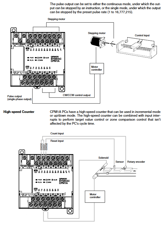
High speed counter: 5kHz single-phase/2.5kHz two-phase
Pulse output: 20Hz~2kHz, controlling stepper motor
Input interrupt: 2/4 channels, response 0.3ms
Fast response input: minimum 0.2ms pulse
Interval timer: 0.5ms~319968ms interrupt
(3) Expand memory
CPM1-EMU01-V1: Program download, supports EEPROM storage
Maintenance and Safety
Regular inspection: power supply, environment, wiring, installation and fastening
Relay lifespan: 150000 times for resistive loads and 100000 times for inductive loads
Safety taboos: Do not disassemble, touch terminals, or modify equipment when powered on
Key questions and answers
Question 1: What is the memory backup method and duration for CPM1A? How to determine data loss?
answer:
Backup is divided into two types: Flash memory and internal capacitors:
Flash: permanently saves user programs, read-only DM area (6144~6599), PC settings (6600~6655), without power failure or loss;
Capacitor: stores read and write DM area, HR area, and counter. It can be backed up for up to 20 days in a 25 ℃ environment, and the higher the temperature, the shorter the backup time.
When the capacitor backup fails, the AR1314 bit will be set to ON, and the corresponding data will be reset. This flag can be cleared through the programmer.
Question 2: What are the output types of CPM1A? What are the respective electrical parameters and usage restrictions?
answer:
Relay output:
Capacity: 2A/point, 250VAC/24VDC, maximum common terminal 4A;
Lifespan: V1 version mechanical 20 million cycles, electrical resistance 150000 cycles;
Limitation: Suitable for AC/DC loads, action delay of 15ms.
Transistor output (drain/source):
Capacity: 0.3A/point, 24VDC, common terminal 0.9A;
Features: Fast response of 0.1~1ms, supporting 20Hz~2kHz pulse output;
Limitation: Only DC load, pulse output must ensure a load current of 0.1~0.2A.
Question 3: How to quickly troubleshoot and solve the fatal error of CPM1A with RUN light not on and ERR/ALM constantly on?
answer:
Troubleshooting steps:
Use a programmer to read error codes and locate the type of fault;
Check whether the program has END instruction, whether the connection of the expansion unit is loose, and whether the memory reports errors;
Check the error flags (AR1308~AR1314) in the AR area.
Common solutions:
No END instruction: Add END (01) at the end of the program;
Memory error: Clear all memory and download program again;
I/O bus error: Re plug and unplug expansion cables to reduce the number of expansion units;
After resolving the issue, clear the error in the program mode and restart the operation.