Omron G9SX series flexible safety unit
Product positioning and certification
Product: Omron G9SX Flexible Safety Unit, used for mechanical safety circuit control
Certification: IEC/EN61508 SIL3, EN ISO13849-1 PLe/Safety Category 4 UL、CSA
Core advantages: logical AND extension, turn off delay, LED diagnosis, high security
Model system and classification
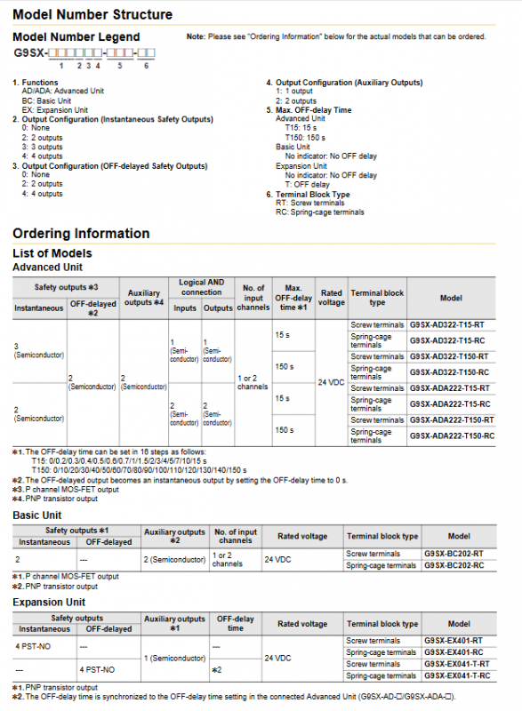
Type, Model, Core Features, Delay Output
Basic unit BC202 has 2 transient safety outputs and 2 auxiliary semiconductor free outputs
Advanced Unit AD322 3 Transient+2 Delay, 1-channel AND Input T15/T150 Semiconductor
Advanced Unit ADA222 3 Transient+2 Delay, 2-channel AND Input T15/T150 Semiconductor
Switching unit GS226 automatic/manual switching, dual safety input T15 semiconductor
Expansion unit EX401 4-channel transient relay output without relay
Expansion unit EX041-T 4-channel delay relay output synchronous host relay
Core functions
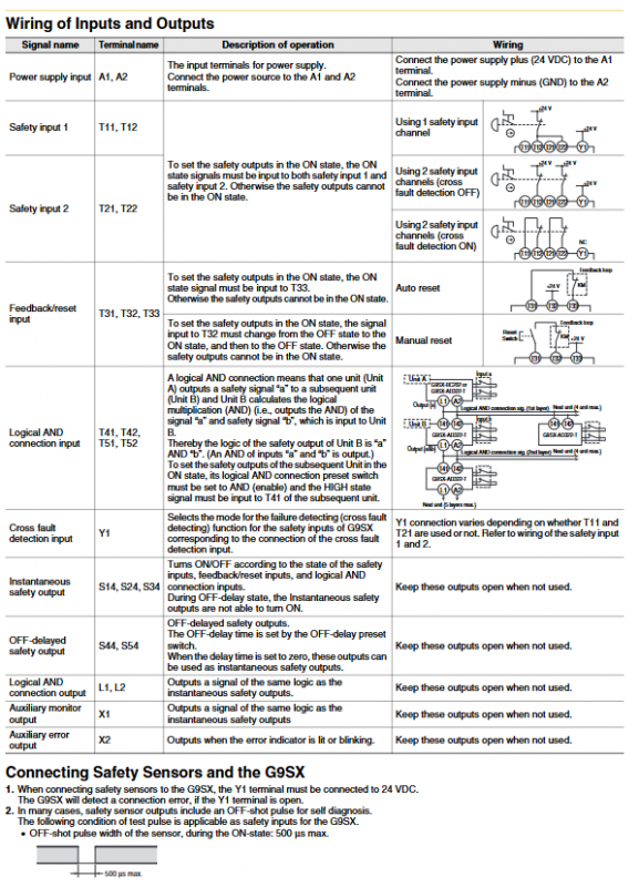
Logical AND connection
Up to 4 units can be connected to a single AND output
Cascade up to 5 layers, total number of system units ≤ 20
The longest cable is 100m
Turn off delay function
T15:0~15s, 16 levels adjustable
T150:0~150s, 16 levels adjustable
Set the delay to 0s to convert to transient output
Reset mode
Automatic reset: T32 short circuit+24V
Manual reset: T33 short circuit+24V, pulse reset required
Cross fault detection
Y1/Y2 open circuit: enabled, detect input short circuit
Y1/Y2 connected to+24V: disabled, compatible with safety sensors
fault diagnosis
Indicator lights: PWR (green), T1/T2 (orange), ERR (red), etc
Fault type: input, output, power supply, expansion, AND connection fault
Protection: output lock, alarm output
Electrical specifications
Power supply: 24VDC, range -15%~+10%
Power consumption: BC ≤ 3W, AD/ADA ≤ 4W, EX ≤ 2W, GS ≤ 5W
Safe output
Semiconductor: 0.8A/point, parallel installation with reduced capacity to 0.4A
Relay: 3A/250VAC, 3A/30VDC
response time
Start: ≤ 50ms
Shutdown: ≤ 15ms
Delay accuracy: ± 5%
Wiring length: All input/AND signals ≤ 100m
Wiring and terminals
Power supply: A1 (+24V), A2 (GND)
Safe input: T11/T12, T21/T22 (dual channel)
Reset: T31/T32/T33
AND connection: Input T41/T42, output L1/L2
Safe output: Transient S14-S34, Delay S44/S54
Auxiliary outputs: X1 (monitoring), X2 (fault)
GS specific: Mode M1/M2, External Indication UA/UB
Installation and usage specifications
Installation: DIN rail, leave 25mm around and 50mm up and down for ventilation
Wiring: wire diameter 0.2~2.5mm ², screw torque 0.5N · m
Protection: Inductive load parallel freewheeling diode/surge absorber
Maintenance: Daily functional checks, regular inspections every six months
Typical applications
Parts processing machine: emergency stop, complete machine stop, light curtain partition stop
Machining Center: Multiple safety doors with independent control zones
Semiconductor equipment: shutdown in the corresponding area when the protective cover is opened
Robot System: GS Unit Automatic/Manual Mode Switching Safety
Key questions and answers
Question 1: What is the maximum size and limit of logical AND connections for G9SX?
answer:
Single AND output can connect up to 4 units at most;
Up to 5 layers can be cascaded in series;
The entire system can have up to 20 basic/advanced units;
A single advanced unit can accommodate up to 5 expansion units (EX);
The maximum length of the connecting wire is 100m, and a two core cable or shielded wire must be used.
Question 2: What are the specifications for shutdown delay? How to set up? What will happen if there is a setting error?
answer:
The specifications are divided into two levels: T15 (0-15s, 16 levels) and T150 (0-150s, 16 levels);
Settings: The two dip switches before and after the host must be consistent;
When the delay is 0s, the delay output is converted to a transient safety output;
If the front and rear switches are inconsistent, the unit will report an error and lock the output.
Question 3: What are the differences and applicable scenarios of the automatic/manual switching function of G9SX-GS?
answer:
Automatic switching: If either of the dual safety inputs (A/B) is valid, the output will be valid, suitable for collaborative work between humans and equipment (such as dual light curtain protection);
Manual switching: select A or B input from the mode switch (M1/M2), suitable for normal/maintenance dual-mode switching (such as door switch+limit switch);
Switching response: Mode switching time ≤ 450ms, otherwise an error will be reported;
Output: UA/UB indicates the currently disabled channel, facilitating on-site status confirmation.