Installation Instructions for KEYENCE XG-8000 Series Line Scan Camera Version Vision System
Positioning and Applicable Scope
Special Installation Manual for XG-8000 Series Line Scan Camera, aimed at XG-8702L (P)/8502L (P) controllers and XG-HL02M/04M/08M line scan cameras, used to guide system safety installation, hardware connection, initial debugging, communication configuration, and specification confirmation.
Safety and regulatory requirements
1. Security level
Power supply: Only 24VDC is allowed, and overvoltage is strictly prohibited
Environment: Moisture and dust proof, away from high pressure, avoid vibration
Operation: Power off wiring, prohibit disassembly, do not turn off the power while the program is running
CE:EMC Class A, Cable * * ≤ 30m * *, with magnetic ring added
2. Prohibited scenes
Human safety protection, explosion-proof environment, direct sunlight camera
Hardware composition and interfaces
1. Core model
Type, Model, Key Parameters
Controller XG-8702L (P) high-end, supports 8192 pixel line scan
Controller XG-8502L (P) comes standard and supports 4096 pixel line scan
Line scan camera XG-HL02M 2048 pixels, minimum line scan 24 μ s
Line scan camera XG-HL04M 4096 pixels, minimum line scan 24 μ s
Line scan camera XG-HL08M 8192 pixels, minimum line scan 45 μ s
2. Expansion unit
Light source expansion: CA-DC21E, 2 channels/unit, up to 4 units
Communication extension: CA-NCL10E, supports CC Link
Camera Expansion: XG-E800, up to 2 line scanners/4 table arrays
3. Standard interface
Power supply: 24VDC ± 10%
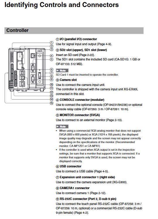
Camera: Dedicated CA-CH high-speed line
Communication: RS232C × 2, Ethernet USB2.0
I/O: 20 in/36 out, high-speed trigger, flash synchronization
Storage: SD1/SD2 dual card slots, supporting SDHC
Installation and wiring specifications
1. Installation requirements
Direction: Install according to the markings and do not invert
Ventilation: Up, down, left and right * * ≥ 50mm * *, front * * ≥ 90mm**
Fixed: DIN rail or M4 screw
Camera: Insulated installation, with a reserved space of 30mm above
2. Core wiring
Power supply: AWG14~22, grounding class D ≤ 100 Ω
Camera: Only using CA-CH series high-speed cables
Encoder: RS422 wire drive or 24V open collector
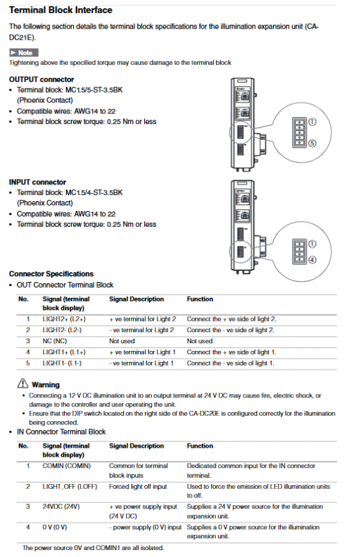
Light source: CA-DC21E, DIP switch selection 12V/24V
Communication: Ethernet Category 5e cable, USB only connected to dedicated software
Initial installation and debugging process
Power on initialization: language, resolution (SVGA/XGA)
Encoder enabled: offline configuration, select RS422/open collector electrode
Light source activation: Process diagram turned on, select DC constant light
Image acquisition settings
Mode: Fixed acquisition/Continuous acquisition
Trigger: Timing/Encoder Synchronization
Parameter: Shutter * * ≥ 3 μ s * * faster than the line cycle
image calibration
Brightness/sharpness LED adjustment
Shadow correction (uneven light compensation)
Line scanning intensity calibration tool
I/O and Communication Specifications
1. I/O parameters
Input: 26.4V max, ON voltage * * ≥ 10.8V**
Output: NPN/PNP, 50mA/point, 8-channel high-speed flash
Encoder: RS422 differential, 5V/150mA output
2. Communication ability
Interface speed usage
RS232C 9600~230400bps no protocol/PLC Link
Ethernet 10/100/1000M TCP/IP, FTP, EtherNet/IP
USB 2.0 PC software connection
CC Link 156k~10Mbps remote device station
Core Performance Specifications
1. Controller
Processor: Multi core DSP
Program: 1000 units per card, external switching
Image: 1000 images per program, JPG/BMP
Working temperature: 0~45 ℃
2. Line scan camera
Sensitivity: Monochrome CMOS
Line frequency: HL02M/04M 41.7kHz, HL08M 22.2kHz
Shutter: 2 μ s~20000 μ s
Lens: C-Mount/Dedicated M40
3. Light source module CA-DC21E
Output: 2 channels, 12/24V switching
Power: 30W per channel, total 40W
Response: 1ms~20ms
Temperature: 0~50 ℃
Software support
XG VisionEditor: Process diagram editing, interface DIY, simulation
XG VisionTerminal: Remote Desktop, Log Collection, File Transfer
Support: Windows XP/Vista/7
Key questions and answers
Question 1: How many line scan cameras can be connected to the XG-8000 line scan system at most? What are the mandatory requirements for wiring and expansion?
answer:
Supports up to 2 line scan cameras;
Must be paired with XG-E800 camera expansion unit+XG-EC80L line scan input unit;
The camera must use a CA-CH dedicated high-speed cable, with a maximum length of 10m and an amplifier that can reach 30m;
Maximum power supply current: 3.8A for dual cameras, requiring a 24V/6A or higher power supply.
Question 2: What are the reasons for the stretching/compression/offset of line scan camera images? How to quickly make corrections?
answer:
Reason: The triggering cycle of the line does not match the workpiece speed, and the shutter speed is unreasonable;
Correction method:
The shutter must be faster than the line period by more than 3 μ s;
Move down the image → reduce the line period; Move the image up → Increase the line period;
Calculate the number of rows based on the field of view accuracy as the target height divided by the pixel resolution.
Question 3: How to set the voltage and wiring for the CA-DC21E light source expansion unit? How many light sources can be carried at most?
answer:
Voltage: Set 12V/24V through DIP switch, which must be consistent with the rated light source;
Wiring: Input terminal connected to 24VDC, output terminal connected to positive and negative LED lights;
Quantity: 1 CA-DC21E with 2 channels, system maximum 4=8 light sources;
Protection: With overcurrent protection, attention should be paid to heat dissipation and continuous lighting time for strong light.